
(from audio-heritage.jp), similar but different as explain in the text
|
| Fig.1, From the original brochure of Yamaha, the PX-2 and with mouse hover the inside the PX-1 (from audio-heritage.jp), similar but different as explain in the text |
All trademarks mentioned and links are presented here for informational purposes only and to confirm statements made by the author. The author of these pages DOES NOT receive any remuneration from the mentioned brands and the listed links.
In any case if you decide to use the suggestions on this page you do so at your own risk. Repairing electronic equipments, even just opening it, can put your life at risk, so don't do it.
If you do not accept and/or not understand the statements in this disclaimer, written in blue, exit from this page immediately.
Everything exposed in this web page is only a suggestion, probably you won't obtain the aim from you prefixed following it.
Be carefull, a true collector is looking for a) original items without any replaced parts, and with all accessories b) or if a Critical Restoration has been done that it is possible to go back to the original version.
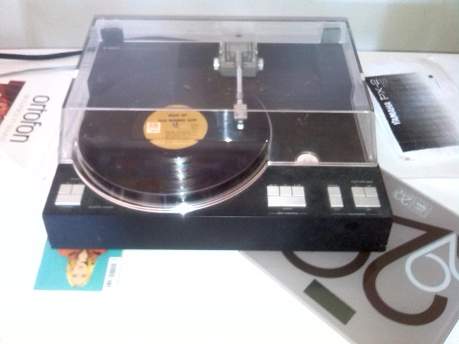
A friend bought this "perfect" yamaha PX-2 used then realised that the arm moved little and badly, arm lift do not work, when run the cartridge rests heavily on the disc, no further test are possible.
Ask the seller and you get that the turntable has come in from a repair man but still has a problem with a belt!!
After a few hours of work it turns out that this is not a repair, the turntable have many faults, needs a real restoration
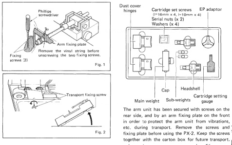 |
| Fig.2, From the owner manuals of PX-2, the accessories list, more and more missing. Click here to large image |
One other main problem are missing parts, some impossible to find today. Please refere to previous Fig.2 for missing as: arm fixing screws in fig.2, second headshell in upper right, arm clamp and screws in fig.1. More there are a BIG problem, the subweights are not present.
NEVER BUY A YAMAHA PX-nn TURNTABLE WITHOUT ALLA PARTS OF Fig2, OR PAY 100 EURO AND BE READY TO SPENT 1000 FOR PARTS. Check the presence of CARTRIDGE SETTING GAUGE, the gray parts on the right in Fig.2.
I won't tell you how much he paid my friend this disaster.
Never buy a quality turntable like this unless all the accessories and all the additional parts that were in the packaging at the time of sale are present, never. If they are not there they indicate sloppiness, disinterest, carelessness, lack of affection for the turntable and disrespect for the buyer.
In next page, upgrade, we make a tentative to build some of those parts but spending a lot of time, pay more, and obtain a solution but NOT original.
Why restore it?
This is the little brother of the famous PX-1 considered one of the best turntables in the world, but very few have come out of Japan. There is also the PX-3 but to cut costs, cut here and cut there little remains.
Probably only 3000 was produced, some massacres (as you can see in Internet with blu led), others degenerate with use, others in Mint-Condition.
Finding a PX-2 in mint condition and with all accessories is difficult and prices are consequential, here an example with almost all accessories and here another PX-2 in box.
Over the years, I have had the pleasure of getting my hands on other tangentials, such as: Goldmund T4 and T3, Rabco ST-7 also with rubber belt, the Marantz SLT-12 impossible to keep in service, a Technics SL7 too complex and, at least by me, not repairable (see a not my photo on the internet).
In Italy there are famous audiophiles who have been writing for 40 years in the magazines of the sector, to one of the most famous is attributed this sentence: "Moreover, which, at least on paper and according to what you read on the net, are the best? I have read flattering reviews of the following turntables, all aesthetically splendid: - Yamaha PX-1 (in Bebo Moroni's opinion the best of all) - Pioneer PL-L1 - Diatone LT-1" (from GFF1972) .
Also I am a chemist with the hobby of HiFi, tube amp, and restoration from my early life. With the hobby of restoration I have the opportunity of "ear" some equipments impossible to buy for me.
The real story is not to describe the Yamaha family but to describe the tangential reading of a record. Let's remember that engraving began on a cylinder, 1877 Thomas Edison patents, with the size of a bean can, in wax hardened with filler, in which both reading and engraving were done by the identical movement. Years ago we did two master's thesis on the preservation of said cylinders, a true restoration was impossible, we recommended digitisation with the passage on VARIOUS supports.
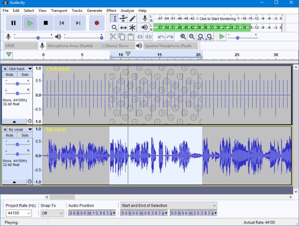 |
| Fig.3, Audacity software is copyright 1999-2023 Audacity Team. Web site: https://audacityteam.org/. It is free software distributed under the terms of the GNU General Public License. The name Audacity is a registered trademark |
Part of history are definitely in the original brochures which describes well the function and the parts (although the picture on page 6 is false, the PCB is upside down).
And finally, to understand how a turntable arm really works, we can have it explained to us (in 1980) by S.K. Pramanick, former engineer at Bang-Olufsen.
This is not the place to describe the difference between tangential tonearm and radial tonearm.
Have you ever repaired a wall watch from the early 1800s made by Lawson in Brighton? NO. Then DO NOT venture into the repair of Yamaha PX-n series tonearm. The risk of disrupt completely a collectible device is really high, and collectors need ONLY original parts.
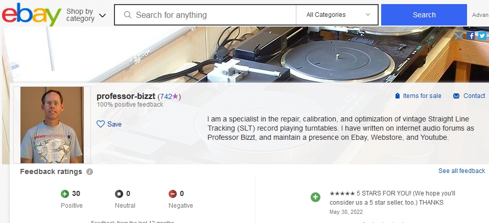 |
| Fig.4, copy of Professor Bizzt web page on Ebay, ancient |
As in one other my web page on Quad II restoration, fortunely there is "a wizard" of the PX-n series repair. It is not easy to contact but this is her sales page by Alan, aka Professor Bizzt. of course I don't know if Alan is really a professor (yes I am) but his work always gets positive comments, and as always if you rely on a specialist you don't ask how much it costs (a famous Italian phrase: Marco how much would a boat like yours cost me, Gigi if you ask how much it costs you can't afford it).
Also I LIKE the statement of Bizzt about hobbist and guru, cited below
Professor Bizzt, Feb 5, 2011
PX-2 Tonearm Drives? What's really original?
I could be wrong, but I see a what may be premature conclusions developing and solidifying here.
The last thing we need in this hobby is more audiophile opinions solidified into "fact" after snowballing from misplaced conjecture and abbreviated analysis.
So I say WHOA, let's slow down here and analyze this with a rational and professional discipline.
Who has the data to show that the two different PX-2 mechanisms have dissimilar reliability track records?
Who has the data to show that the two different PX-2 mechanisms have dissimilar performance characteristics?
Best wishes, Professor Bizzt
There are other technicians who could get their hands on this turntable, depending on where you live. We mention two famous ones more for fussiness than quantity.
The Turntable DOC, the name is enough to describe it. And the Liquid Audio a nitpicker, but you can do even better (will he be happy with the compliment?).
Repair and restoration are not synonymous. Italy has the largest number of cultural sites recognized by the UNSECO, its history, from Neolithic, to the Romans to the Renaissance makes fit a reference in the field of Cultural Heritage, not marvel that techniques, methodologies, procedures and ideas about restoration have been developed, with even a careful terminology to describe the "types" of restoration.
It is difficult to explain the difference to non-experts, in universities, Prof. Giorgio Bonsanti is often mentioned for his "Paradox of Brustolon", "if a chair breaks, he is repaired. If the chair is from the Brustolon, it is restored" (Andrea Brustolon, was an Italian sculptor in wood in 1700. He is known for his furnishings in the Baroque style and devotional sculptures).
Again in the restoration of Quad II I have spent many. many words on this subject, you will find everything on previous web page.
As soon as this "endless" restoration work is finished, I think a professional audio repairman would ask for at least 1,000 euros, perhaps building parts that no longer exist, worse damage could cost 1,500 euros to restore (bearings, transformer, rubber parts, etc.).
In your dictionary probably there is not the word "destroration". It is contraction of two word Destruction and Restoration, invented by history teacher Dr. Benni Leemhuis describing an intervention on a Egypt Pyramid.
Some example of Destroration are often cited by art historians, an example can be obtained reading this page.
What about Yamaha PX-1, PX-2? As already written above a true collector is looking for a) original items without any replaced parts, all accessories, better with original box, b) or if a Critical Restoration has been done that it is possible to go back to the original version.
Lacking the previous 2 statements the object (not only for me) has a value of zero euros.
Some example of Destroration of PX-2 and PX3 are available on Internet, as:
However, there are cases in which a critical restoration (or even more a scientific restoration) is very difficult and for which the cost exceeds a lot of commercial value.
It is not the fault in Yamaha PX-2 but of those who used it without any respect or without regular maintenance probably are a non working turntable.
Let's repeat, it's not a defect, but servicing a tangential arm is within the reach of 10 technicians worldwide. But if you have an Alfa Romeo 8C 2900B, how many restorers (let's not call them mechanics) know how to get their hands on it?
Zero lack (shameful), the immoderate use of unobtainable components, perhaps produced in 100 examples and then disappeared, the arm motor, the solenoid, some LEDs, some diodes and more. Some are used here with unnecessary complexity, see IS1555=1N4148, others have NO substitutes see 2SD669 in the starting circuit of the unobtainable solenoid.
This technological bravado puts the equipment at risk, one damage to one of these components and the turntable becomes a heavy doorstop.
First lack (insoluble), in the photos of fig.5 there is a major design problem in the PX-2 and PX-3: the arm is NOT that of the PX-1. As you can see from the PX-1 owner's manual, the arm is driven by a worm screw like the one that moves the lacquer engraving arm.
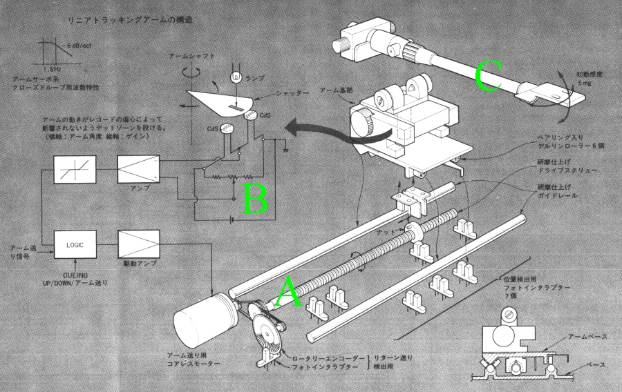 |
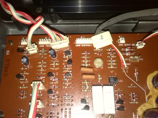
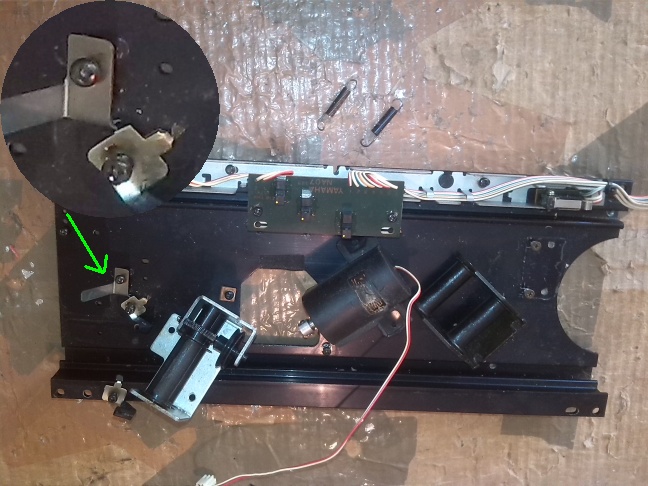
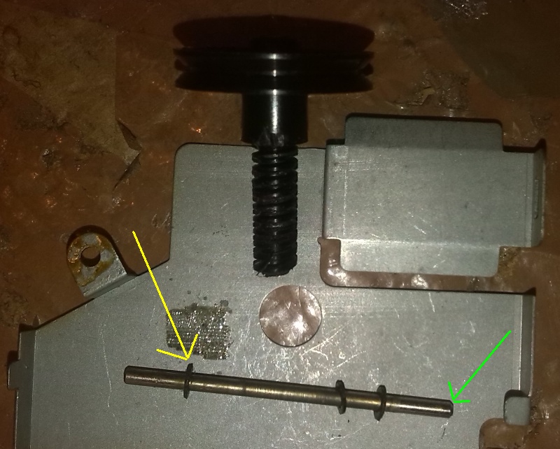
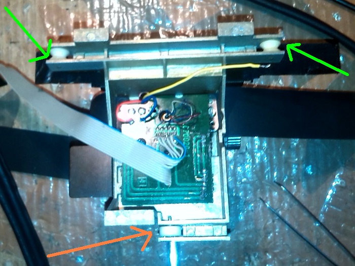
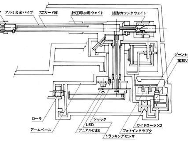
| Fig.5, green point A indicates the screw that moves the arm with an optocoupler encoder disk for speed measurement at its side
. Point B indicates the arm deflection relief system, similar but more efficient than that of the PX-2 using a center tap. The point C shows the absence of the collar that slides over the arm to set the cartridge weight. To make the weight you move the counterweight as in 80% of the tonearms |
Every choice has its problems, if you ever open the bottom of a PX-1 you will find the bravado of the technicians pushed to an unattainable level, even with the Service Manual (which as usual contains half the instructions) restoring it would be a feat.
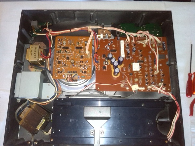
Second lack (difficult to solve), the best turntables have separate power supplies. Some have only the transformers outside, others move the whole power supply section outside (like the PX-1). By reading the circuit diagram and looking at the inside (fig.10 on the left) the problem can be partly solved by moving the transformers to an external enclosure.
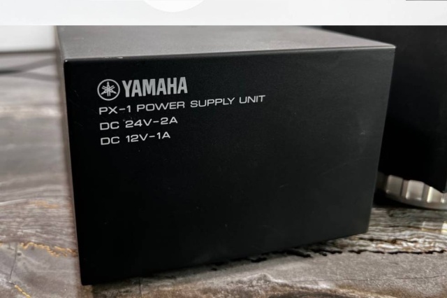 |
| Fig.6, the external power supply of PX-1, the front side photo show the DC voltage send to the turntable (from aucview.aucfan.com/yahoo/d1052241526/). The internal photo, with mouse hover, show the complexity of the supply and voltage stabilizer. More and more photo of internal of PX-1 are show in Good Old HiFi page |
Given the amount of work required, an EMI filter and perhaps a remote turn-on system can be added.
Third lack (difficult to solve), the foots balance. The four feet (or three) of a turntable are expected to be burdened with the same weight. I think only the Italian manufacturer of the Vyger turntable (by Giuseppe Viola and Enrico Datti) is careful about balancing the support points. Having 5 Kg for each of the four feet for a 20 Kg turntable can only be good.
It is not a lack of this turntable but ALL have an unbalance on the foots, probably only 2 or 3 are ok.
Maybe it is better to say it but there is no connection between this site and Vyger brand, only esteem for their work and passion for audio.
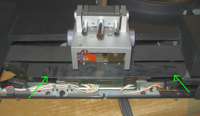
Fourth lack (can be solved), flat belt tension. It is unbelievable that whoever designed the arm, indeed whoever designed the transport system, did not foresee a flat belt tensioning system. Yet he had everything ready, even a bracket with slots already made.
Sloppiness or downgrading? Probably the latter since they all brand do it, the one that costs less 'must' be worse. Referring to fig.14 and fig.17 in the caption a possible solution, but we will not adopt it for now.
Fifth lack (impossible to solve). the up and down function of the arm does not work as in 1000 other tonearms. Usually gravity pulls the arm down, depending on cartridge weight, and some mechanical/hydraulic system raises it when needed.
Here it works in reverse, an electromagnet "pulls" the arm downward, and without power a spring push the arm upward.
Cartridge weight is NOT affected by this but it becomes impossible to do cartridge alignment, weight, azimuth, VTA with the turntable switch off.
Unless by luck or stubbornness you find some undocumented function to stop the platter with tonearm down (if we write it down it means that a solution exists).
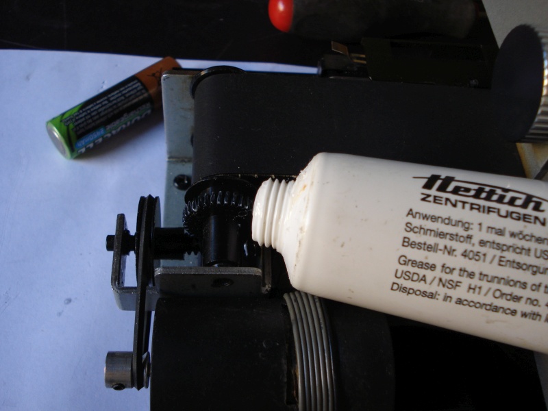
Sixth lack (difficult to solve), Up and Down of the arm are controlled by push buttons, which, as mentioned above, activate the solenoid but the movement is "braked" by a brass cylinder in which a steel piston slides, on the surface of which grease is spread (see Fig.65 and Fig.66).
Either the grease dries and the descent is very slow, or we change it and the arm "falls off", damaging our expensive ruby cantilever.
Starting with the third defect, we can measure how the weight is distributed over the 4 feets. Maybe we can do something to balance the turntable during restoration.
 |
| Fig.7, see the Ortofon bubble, centered, we can weight the four angles. With mouse hover, see the front right side |
A few books of the right thickness, an Ortofon bubble and a weighing scale are enough for our investigation. we place the scale on each side, put the turntable back on the bubble and get the table below.
| Tab.1 weight on the four feets of Yamaha PX-2 | ||
| in Kg | left | right |
| rear | 6.3 | 4.0 |
| front | 3.4 | 3.7 |
The total weight, 17.4 Kg, matches what is stated in the manual taking into account the disc and cartridge. The imbalance is evident.
 |
| Fig.8, only 3 screws to remove the metal bottom that rests, just barely, on many turrets on the perimeter of the metal case, probably the bottom cover can be fixed better |
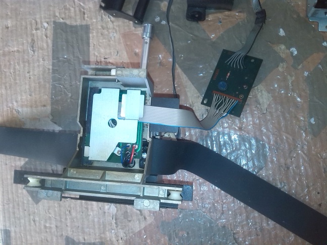
Next step remove the arm and its base. There are some screws to remove, but first the four connectors must be disconnected..
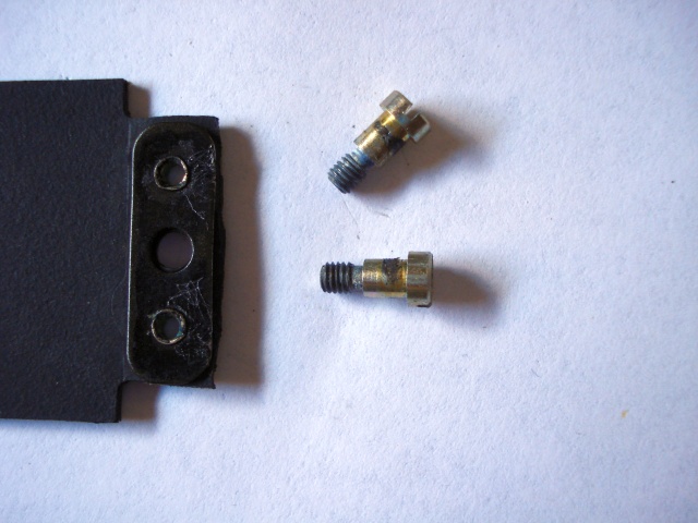
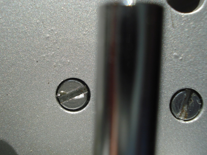
Unfortunately, one can already see that the turntable has been tampered with by some wafflers who tried to repair it. The screws are of random shape and length, some long bronze coloured, others short and black.
 |
| Fig.9, If you have forgotten how the cables from the arm were positioned, you can use this photo. On the right you can see one of the first problems, the infamous glue used by almost all manufacturers in the 1990s, which after 30 years degrades and becomes corrosive |
Tonearm removed
With the whole arm system removed, we can put the main case on a shelf and analyse the problems of the tonearm, the track problems, the dragging problems. Yamaha produced only one arm with the worm gear, for the PX-1 and two arms with the belts, the YA-27 for the PX-2 and the YA-32 for the PX-3 (although the latest PX-2s mounted the YA-32).
Better the YA-27 or the YA-32? We don't know, but it is easy to recognise them, the YA-27 has only one rubber belt, the other has three. Also the old YA-27 have 2 nuts to fit subweight for heavy cartridges.
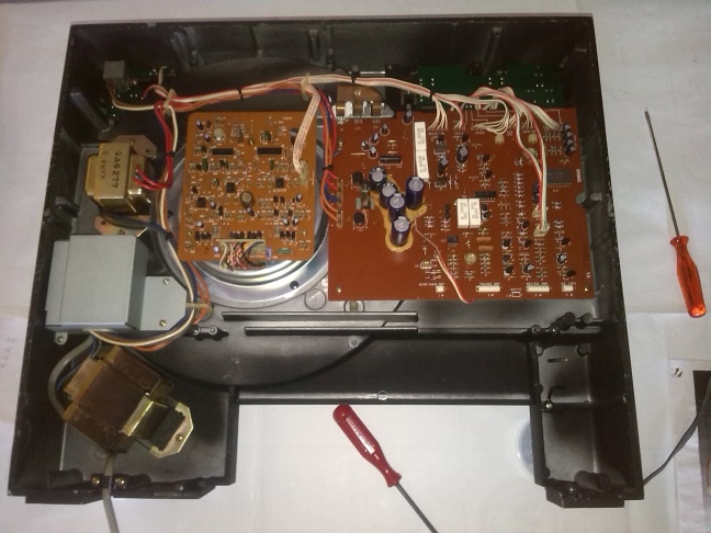 |
| Fig.10, tha main case without tonearm (see the 2 transformers on the left side) |
Let's look at some close-up photos and start with the comments, first the famous-infamous springs. In the photo captions the comments.
 |
| Fig.11, the famous springs with their original appearance, note the flat cable on the right soldered directly to the PCB |
In Fig.11 we see the arm-system front view, in fig. 12 see a rear view.
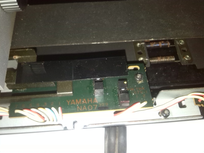 |
| Fig.12, Seen from behind, the system shows photogates (Slotted Optical Switches) and a strip of plastic that is too small to prevent external light penetration |
Next step is a underview of the PCB and soldering.
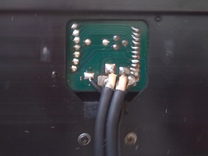 |
| Fig.13, the PCB in fig.11 seen from below. Another problem: it looks like it was NOT designed for this output cable but for a much thinner one. They had to bend it and the ground wire is on the wrong side too. The shields of the 2 channels almost touch each other. Careful insulation work on the 5 output wires will be needed |
In order to remove the belts and get the arm out of the rails, DO NOT TOUCH THE SPRINGS but ....
 |
| Fig.14, looking at the arm from the front, on the right, under the belt you can see a life that retains the pulley castel. Removing the screw in the photo we find stripped. There is another screw on the other side. Fig.17 shows the factory slots, by cutting two more on the other side of the frame, a belt tensioning system could be constructed |
Once the pulley castel of Fig. 14 is removed, there is no longer any tension on the belts and the springs can be easily released. The arm comes off from the rails from the right, side of fig.14. Once the arm has been removed, the other pulley castel and the motor have to be disassembled.
From an old restorer's a trick: you have unscrewed a screw, well, put it back in its place with a couple of turns so you won't lose it and you won't have problems if they are all of different shape and pitch.
 |
| Fig.15, the track supporting the tonearm freed from its pulleys and motor |
We now have the arm removed from its track/rail ready for diagnostic investigations. As seen in fig.11 the flat cable is soldered to the PCB, we have to unsolder the output RCA cable, fig.13, and remove the whole PCB.
 |
| Fig.16, the arm upside down, with the belts and the PCB, which we do not recommend desoldering for the time now |
Now we can proceed with the diagnostic phase to see if any components are faulty, broken, and if there are any other hidden problems.
Diagnostic before restoration
The diagnostic phase is essential and the most important step. Be carefull:
first) NEVER CHANGE THINGS THAT WORK, and to understand this you have to measure them!
second) DESIGNERS ARE NOT IDIOTS, they may make one mistake in a hundred designs, but if our HiFi equipment has come down to us, in our century, it could not have been so wrong!
Sometimes designers have to deal with budgets, but certainly an object that still works after 40 years will not have suffered too many cuts.
Pulley, gear and frame castle
Let us begin by studying the castles on the right and on the left, see caption under figure for description.
 |
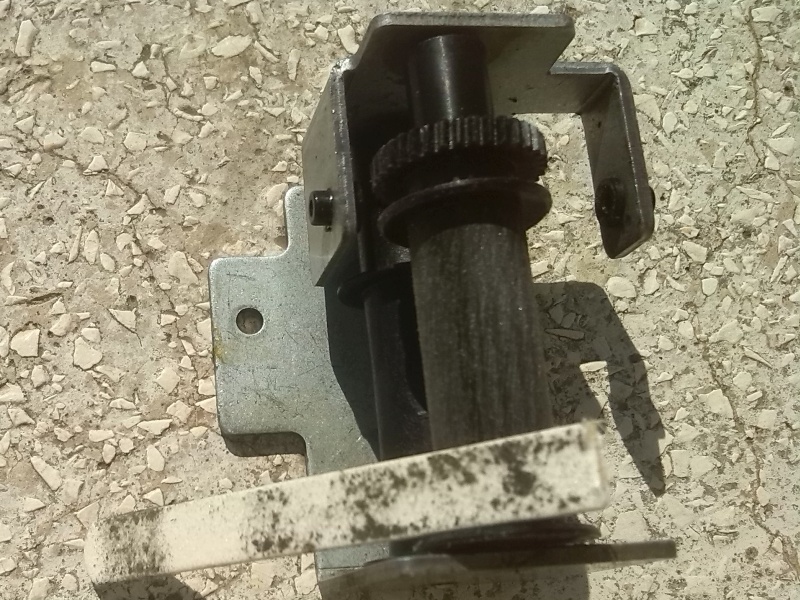
| Fig.17, The pulley pins are fixed and the pulleys turn on them. There is some clearance between the pulley and the housing, very little, which is good because the two pulleys are not braked and turn freely by running your finger along them. The surface is not completely smooth but perhaps it improves the grip on the belt |
If one of the pulleys was braked, it would be necessary (before tightening the springs) to remove the pin, clean the pin and hole, perhaps lubricate, until free rotation is achieved.
 |
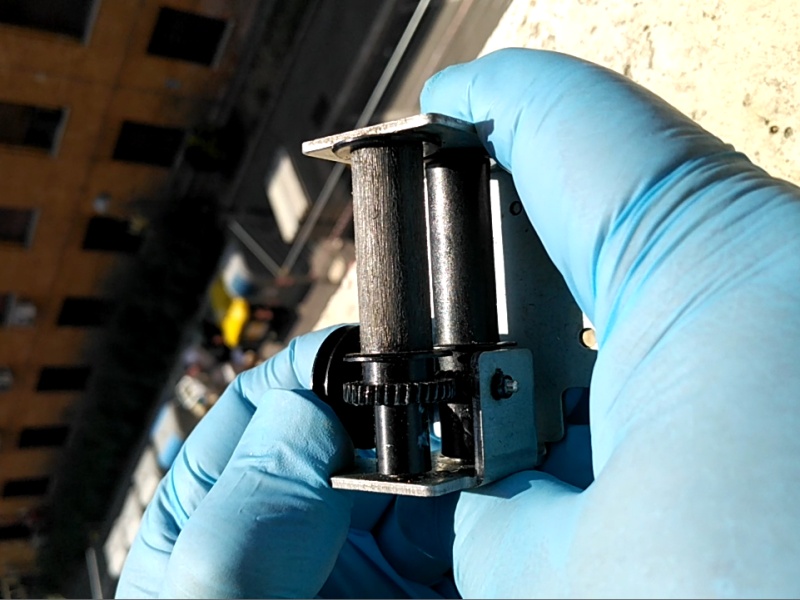
| Fig.18, The left castel drags the flat belt. There are 2 pulleys, one free run and one with gears. The free one must turn like the ones in Fig.17 with a bit of clearance. The one with gears must be disassembled and studied, it's the only one that drags the belt, but how? |
Before removing the gear, we study how the belt is dragged by a smooth-looking pulley (and before tightening the springs). We need a lot of light.
 |
| Fig.19, The pulley dragging on the sun. There are four scratches on the pulley, small grooves, but only every 90 degrees. This is what drags the belt, only this! |
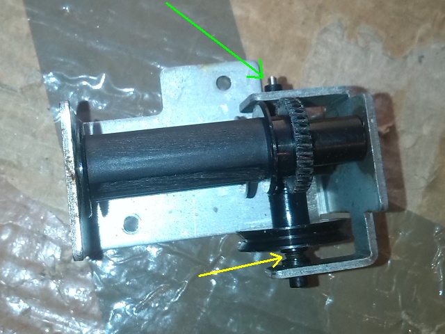
To remove the pulley, the pin in fig.18 must be tightened, see green arrow, and removed, attention to the washers, see yellow arrow, do not lost they.
 |
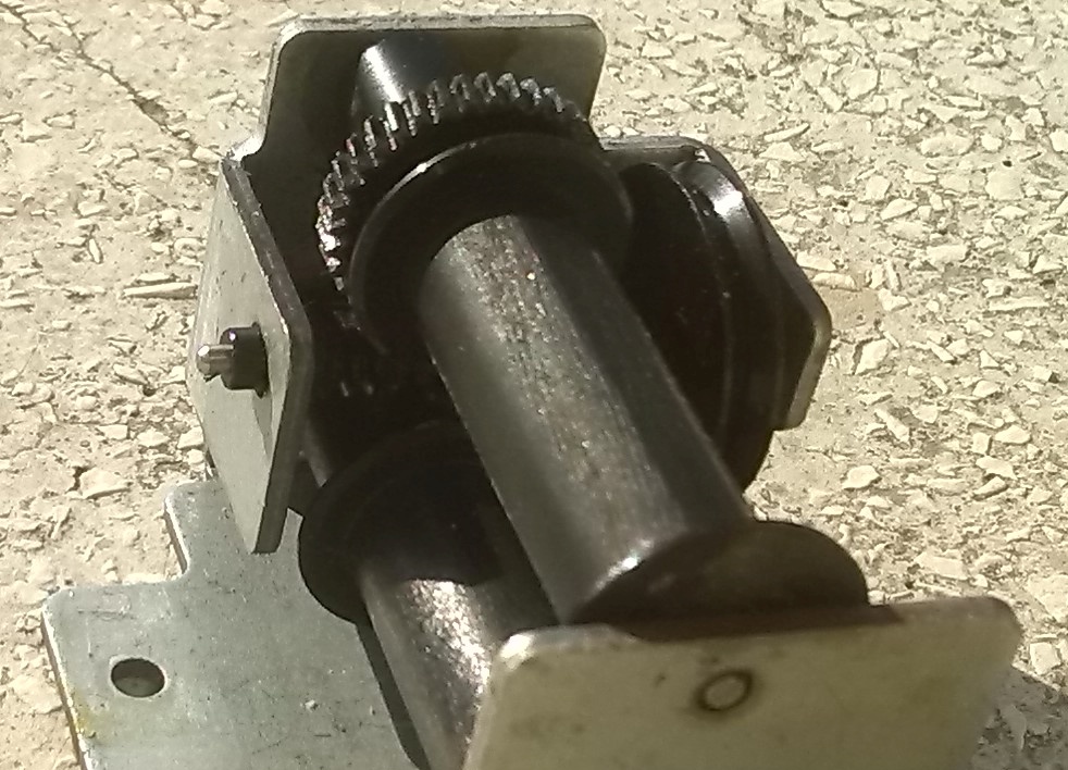
| Fig.20, here is the result.
Mind you, the pin is fixed and the pulley should rotate on it easily. Use the mouse hover to look at the pin, it should be polished and lubricated (before tightening the springs). There are 3 plastic washers, see yellow arrow, two on one side |
First defect, you have to clean both the pin and the gears with alcohol (NOT other solvents that dissolve plastics).
If the plastic gears are damaged the PX-2 could die here unless you can find someone to rebuild them with a milling cutter and lathe (NOT with a 3D printer)
To clean the pin and gears, you can use ethyl alcohol, the kind used to make Limoncello or Nocino, perhaps with the help of a toothbrush.
 |
| Fig.21, washed gear-wheel ready for assembly |
Obtain more grip
This is the second defect, the most common one discussed in the forums, the belt slipping on the pulleys, it can be repaired with a little inventiveness.
Before re-assembly of the left castle (and before not tightening the springs), we must improve the grip of the traction pulley. How to obtain more grip?
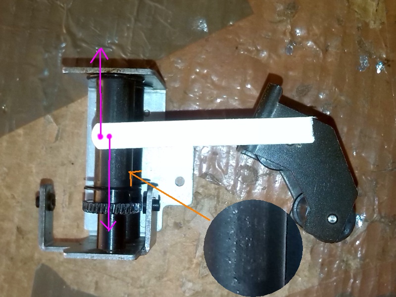 |
| Fig.22, Take a nail file, coarse grain, move 7 times according to the purple arrows while pressing the file with your index finger. Now turn the pulley 30 degrees, repeat for another 7 steps. Turn another 30 degrees, and so on until you reach 360 degrees. Remove the dust with a clean brush |
Since the pulley is made of plastic, probably polyester, if we have scraped well there should be some residue in the file.
 |
| Fig.23, the result of scratching the plastic pulley with the file (but only in the direction of the purple arrows). Not just a few strips but the whole surface is roughened to better drag the belt |
Next step (before not tightening the springs) is to reassemble the gears to see how the traction works, without having disassembled the rest of the arm yet. And find a BIG problem.
 |
| Fig.24, we temporarily reassemble the tracking system and use an AA battery to run the motor. By reversing the polarities it runs in reverse. A BIG problem arises, the three washers in fig.20 are not enough to hold the gear pulley in the centre. There is too much clearance on the pivot |
Third defect, the problem is serious, let us study fig.24:
The erratic movement of the arm sooner or later drives the electronic logic crazy and maybe even those trying to understand why (better not tighten the springs).
 |
| Fig.25, showing how the gear-pulley in fig.20 moves on its pivot, as if a washer were missing, is difficult, let's try with this video. Not missing a washer, the gap will be about 0.5, 0.7 mm |
To solve the problem you have to disassemble everything as in fig.20 (remember to save the washers) and with a bench vice tighten the frame. By moving the pulley by hand you can see how much you have to tighten the frame, in our case 0.8 mm.
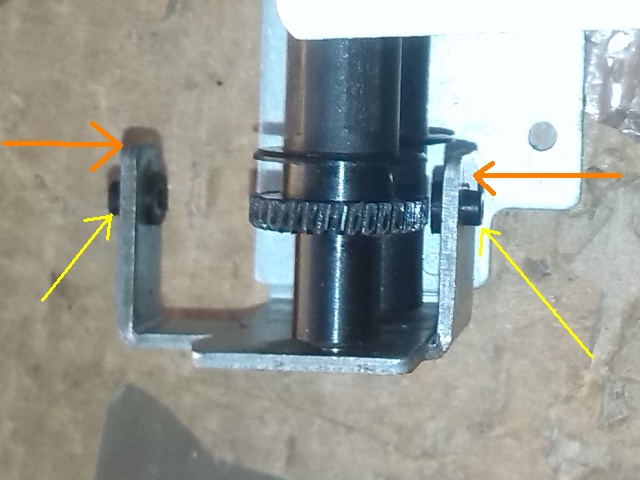 |
| Fig.26, tighten the frame by pressing according to the orange arrows. Do not destroy the plastic parts indicated by the yellow arrows |
After reassembling the two frames having almost tightened the gear pulley movement, you can move on, after a drop of oil.
 |
| Fig.27, and finally the two pulley pins rotate in the holes of the frame (they are fixed to the pulley), so you need a drop of oil before reassembling everything |
Caution: there is probably a PX-2 contrary to this with the frame, pulleys, gears over-tightened that struggle to move, there needs to be a different job to make them move smooth to the right point.
(or you can tightening the springs)
Tracks and wheels
The arm must run on some kind of tracks. Unless we use an air cushion there will be wheels running on these tracks.
 |
| Fig.28, the arm use 3 wheels running on the tracks, 2 on one side (green arrows) and one, flat, on the other, orange arrows |
Clearly these wheels must run free, just test by spinning them with your finger. Fourth defect. Unfortunately, the flat wheel turns with difficulty even by pushing it with your thumb
Such a problem must be solved or the tonearm perhaps will move but fatiguing the dragging system (or better tighten the springs).
 |
| Fig.29, half a drop of oil on each side, directly on the axle, and the pulley has to be moved by hand until it unlocks, then you can use a stick as if it were a violin bow (see this movie) and run the wheel at least 30 times |
If a pulley is really locked it's trouble, pulling out the axle/rod is very difficult, the arm frame seems to be made in Duralumin, strong but fragile, good luck!
The flat belts
The tonearm frame is dragged on its rails by two flat rubber straps, they are well constructed multi-layered composite type and anyone who says they elongate is lying (it seems that saying so will make you famous).
Once they are disassembled one realizes that it would take perhaps 50 kilograms of tension to stretch them, and if there is no traction the problem is another. This is not really the fift defect but the belt must be almost cleaned.
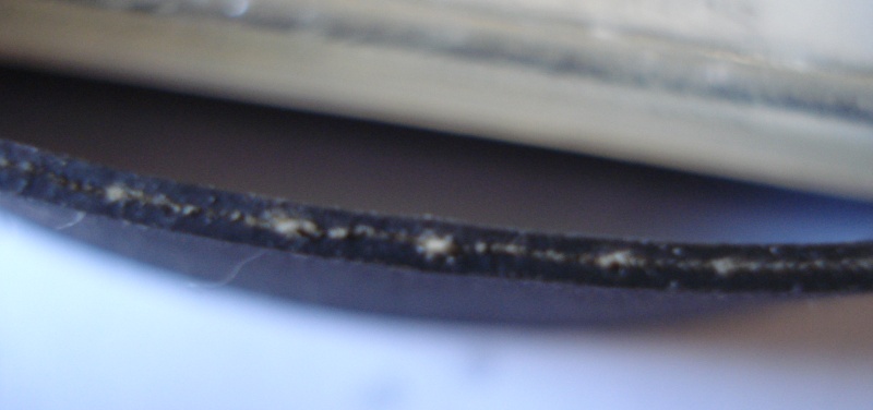 |
| Fig.30, side view (following the cut) the belt shows the composite structure, a fiberglass net and 2 layers of rubber |
Let's reason for a moment, we have 2 belts, that is 4 sides, but only one will have been in contact with the driving pulley and maybe worn out. That still leaves us with three good sides.
If someone followed "the dominant thought" and then having solved nothing left the turntable standing for years perhaps the belts have taken a bend on the pulleys.
Aside from the 100 pieces of nonsense you read on the net one way to soften this kind of rubber is to boil it! In a small pot with lots of water for at least 15 minutes. It also serves for the pulleys of the Lenco, Garrad 301, Thorens TD-124 or similar. In the worst cases you can try a 10-minute boil in a pressure cooker well filled with water.
You don't work miracles, but the rubber will soften, but if the pulley is cracked, decoached, degraded (like woofer foam) you need a new one!
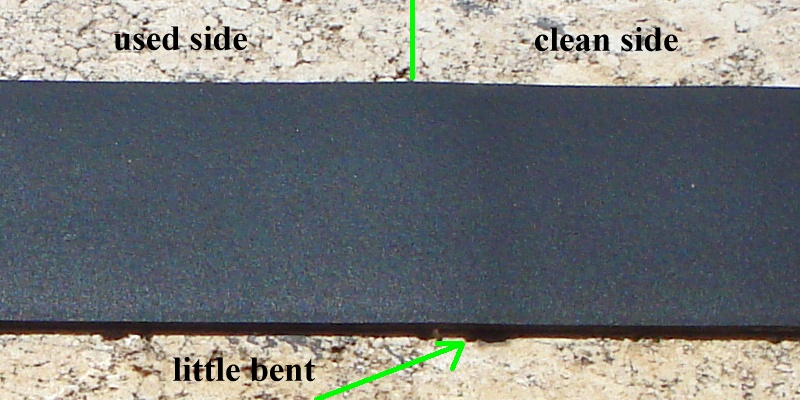 |
| Fig.31, difficult to photograph the belt to show the used area and the new area and the small bend |
These belts are in good condition, still soft, don't need to be boiled, but the exposed side is well filled with dust, they need to be cleaned.
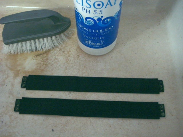 |
| Fig.32, a large sink, good mild soap, a hard brush and a little effort to clean the straps thoroughly. Just 2 washes 2 rinses and let them dry in the sun |
Washed belts are really in good shape, but there are still some other problems.
 |
| Fig.33, everything we touch in this turntable has problems, but where did it live in a basement? Here are the belt screws that need to be cleaned in an ultrasonic bath to save the threads |
Going back to what has been said, if the rubber constituting them is so degraded that it does not adhere to the fibreglass mesh so that the sandwich structure is compromised, in this case they just have to be replaced.
Or if the springs are really too tight, there is a possibility that the belts (after 30 years of tensioning) will loosen a little. The structure of the springs and their load must be redesigned.
If, after all attempts, the belts really do slip, one solution is to use the third hole, see fig. 11, and install a new, weaker but shorter spring, as in this case). The new spring does all the tensioning work and the old springs only intervene when needed.
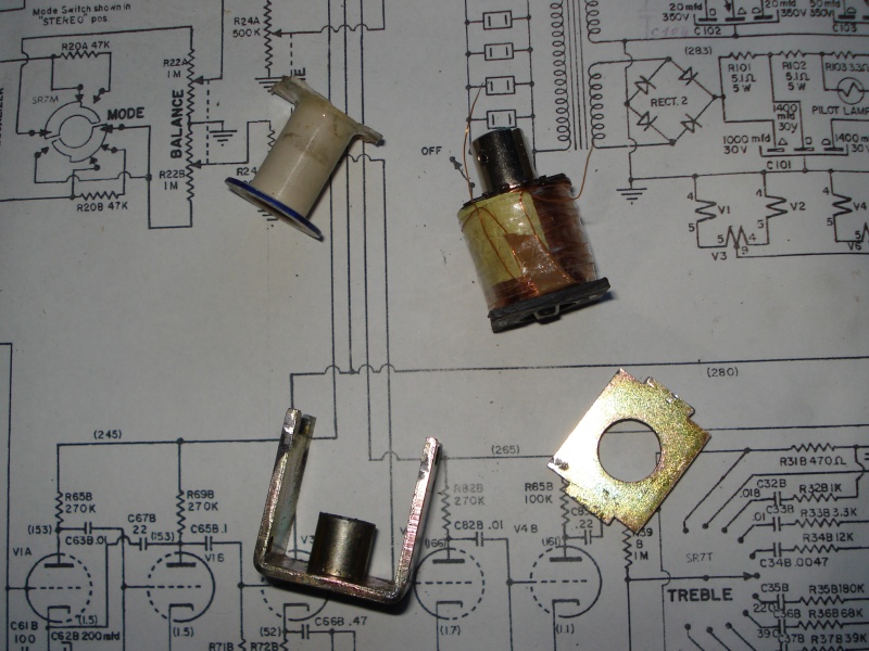
The tonearm motor
The arm frame is driven by a motor, which is a bit strange, in the various versions this is where the changes were concentrated.
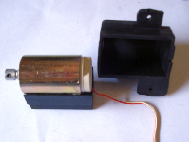 |
| Fig.34, the engine removed from its rubber shell, which has the double function of shielding noise and vibrations |
Since we are taking it apart for diagnostics, let's also see the make and model
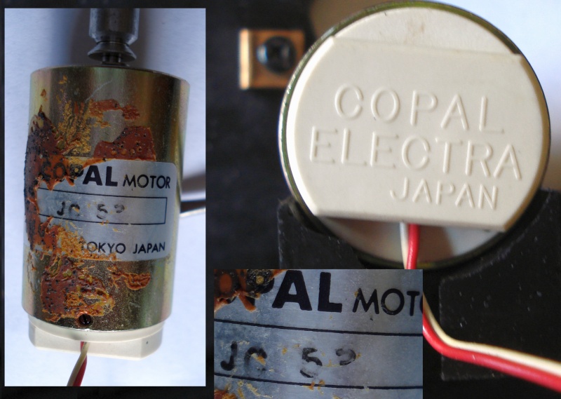 |
| Fig.35, the motor is from Copal Japan, unfortunately the glue (to be put back on) fixing it to the rubber has damaged the label but it is still legible, code JG 53 |
Today there is absolutely nothing to be found on this engine, if it dies it takes the whole turntable with it. With the same dimensions the Copal LS26 is sold, but it looks like a 24V DC.
Is similar the Matsushita KCN-22, 4V DC, used in the PX-3?
You have to be very careful when testing it, already with 1.5V (of an AA battery) it runs well, maybe giving it 12V would kill it.
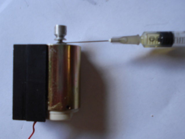 |
| Fig.36, a drop of oil directly on the motor shaft, it is difficult NOT POLLUTE the pulley |
We can finally close the engine in its rubber shell and fix it.
 |
| Fig.37, let's fix the motor, pay attention to the screws with the green arrow, they must be "placed" and not tightened so as not to squeeze the rubber that is over 40 years old, the yellow arrow indicates a spring that holds the stud already discussed in fig. 20, the orange arrow indicates where neoprene glue will be added to fix the flat cable, the purple bar indicates the belt that must remain straight after fixing the motor |
In the original assembly the rubber motor shell is fixed with the 2 screws of the green arrow. Since it is no longer possible to tighten them after more than 40 years, a few drops of neoprene glue can be used between the shell and the aluminium plate to prevent the engine from moving during use.
Checking the functioning of the tracks, the castles with their pulleys and gears, checking the motor, fixing the belts well, a necessary diagnostic, we have already done part of the restoration, now at least the movement produced by the motor will be unrestrained and continuous.
mantra
a word or phrase that is often repeated and that expresses something that people believe in (from Cambridge dictionary).
Right now the new mantra is: tighten the springs, change the photo sensors
Chasing the groove
Cadmium sulfide light dependent resistor (CDS) was used by PX-2 with a slit and a LED to chasing the grove of vinily, see point B in Fig.5, we start by testing the LED and photores. See L9 (TLR121) and CDS (P1234) in the circuit diagram.
For CDS type P1234 none is available after 1 hour of search, as reference here a datasheet of single photoresistors. For LED type TLR121 seem a Toshiba, in Internet exit some strange supplier, here a datasheet of TLR101 up to TLR120.
 |
| Fig.38, the LED L9 according to service manual is TLR-121, check with 10mA |
The L9 LED is not directly visible but its emission can be seen through a providential hole in the PCB of the tonearm.
 |
| Fig.39, we are lucky the LED emits visible light, all we need is our eye as a spectrometer, a yellow-orange light |
But what the hell kind of LEDs did they use, the emission spectrum falls between 560 and 590nm, right where the maximum absorption of CDS resistors is!
If it fault, remember to put in an green LED or a violet one (build the heavy doorstop).
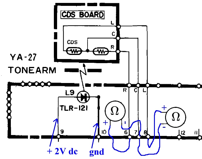 |
| Fig.40, from the general diagram, the circuit to test the 2 CDS, with power supply and ohmmeter |
Now let's see if the two CDS sensors work.
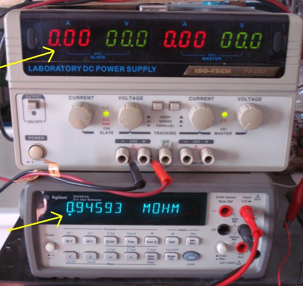 |
| Fig.41, with soft ambient light, no current in the LED and almost 1 Mohm resistance of one CDS |
Next supply voltage to the LED, as shown in fig. 40, and see if the resistance changes.
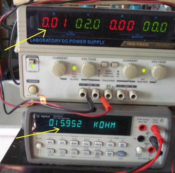 |
| Fig.42, with 10mA current the CDS resistance drops to about 16 Kohm. A small movement, by hand, of the arm changes this value |
With the arm in the middle, the values of the 2 CDS are similar as are the variations on movement.
The mechanical/electronic groove-tracking system, the most delicate part, works!
Arm position sensors
For surely the Slotted Optical Switches are broken, we use a hammer to remove them :-)
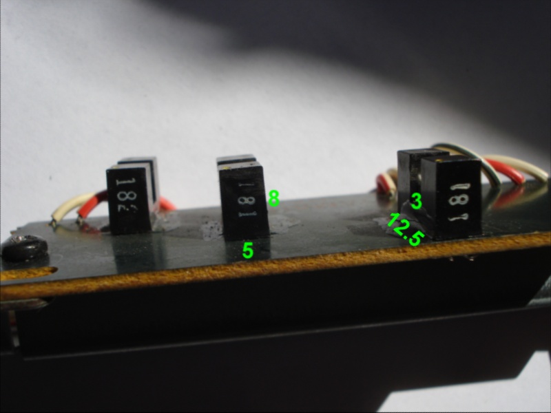 |
| Fig.43, the photo-gate, also called Slotted Optical Switches, are signed 182 and 181, no brand. With caliper we can obtain the measure in mm |
In the service manual are stated as SPI-201, non brand (can Yamaha cite one other brand, never), no datasheet.
It seem a Sanyo component, here you can find the datasheet of SPI-202 up to SPI-214, but the sensor is a single transistor! The SPI-204 and SPI-214 have same case of SPI-201.
The Sanyo SPI-240 have led diode and Darlington as sensor, but a different pinout of SPI-201 and too small case, here the datasheet
As usual, reading the service manual diagram (which at least so far has no errors) extracts the circuit to diagnose the arm positioning system
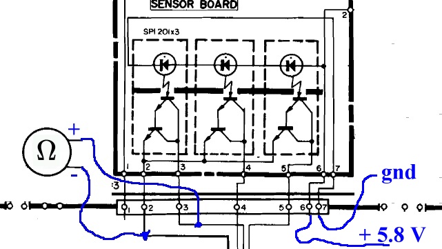 |
| Fig.44, circuit to test the 3 LEDs in series and the Darlinghtons one by one |
In the middel I spent one hour to check Internet and a few Sanyo SPI-201 are available in strange supplier, original?
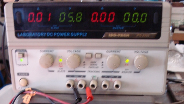 |
| Fig.45, as always 10mA is sufficient to see if an LED lights up and if the required voltage drop is compatible with the datasheet (datasheet ??) |
If the series of LED show 5.8V for 10mA surely is good, check the light.
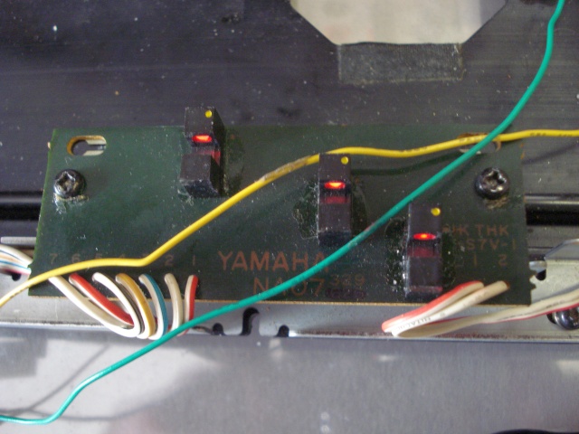 |
| Fig.46, the three LEDs light up, with a dark red colour, we have to investigate |
We need a spectrograph with a fibre-optic input so that we can slip into the slot and measure the emission spectrum of the LED.
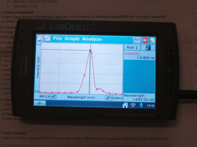 |
| Fig.47, the spectrum of one of the three leds, but all similar, shows an emission in the deep red, at the limit of the human eye's vision, the FWHM is wide, with a peak in infrared |
The emission spectrum is similar to that of the LED in OPB825R, but does not match the other specifications. Even if it work in deep red, the sensors must be shielded from ambient light.
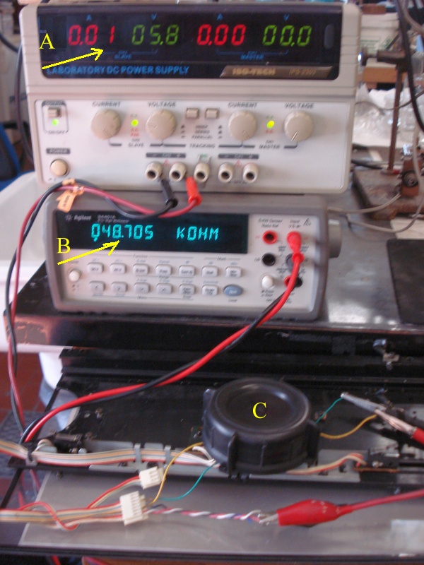
 |
| Fig.48, given the circuit in fig.44, we do not pass current through the three LEDs in series (A) and measure the resistance (i.e. whether there is conduction) of the transistor (B). The three photo-gates should be well hidden from ambient light (C). Better disassemble everything and work on the frame with the tracks (D) |
55.9 Mohm, transistor interdicted, but for the measurement of transistor conductivity, the tester must be set for diode-ohm, but some testers may not produce sufficient Vce voltage. Try an old analogue with needle and 9V battery.
The Agilent (HP) 34410A does not have these problems, it inposes a current by varying the V, but it may cost as much as a shabby PX-2
 |
| Fig.49, with 10mA of current the transistor's conductivity rises to 48 Kohm, a huge difference |
The other 2 photo-gates also behave in the same way. They are sensitive to the ambient light in the cap (C), take this into account.
Yes I know, LEDs are subject to lumen degradation if they a) work at high temperature, b) work with high current pulses, c) work at the limit of SOA d) are subject to continuous vibration and ultrasound. These cases do not seem to exist here and I believe we will never see lumen depreciation in their lifetime.
They certainly work, but perhaps it's better to change them to something similar, perhaps retrieving them from a mouse with a wheel, since the mantra of stupids dictates it (build the heavy doorstop).
Arm position sensors, May2023 update
In April 2023 one of my friends decided he also wanted a Yamaha PX-2 but at a really low price just to try out a tangential arm as he had never had one before. He found a PX-2 that was claimed to be "almost working" but turned out to be stationary for years and with many faults.
Pressing the 30, 25 and 17cm selection nothing happens, but the arm moves well, goes down and up very damped, also does not return to the end of its travel.
This time maybe the photo-interrupters are really broken. The first thing to do is to redesign the circuit, simplifying it to understand how it works. Once this is understood, a more thorough test can be attempted on the SPI-201.
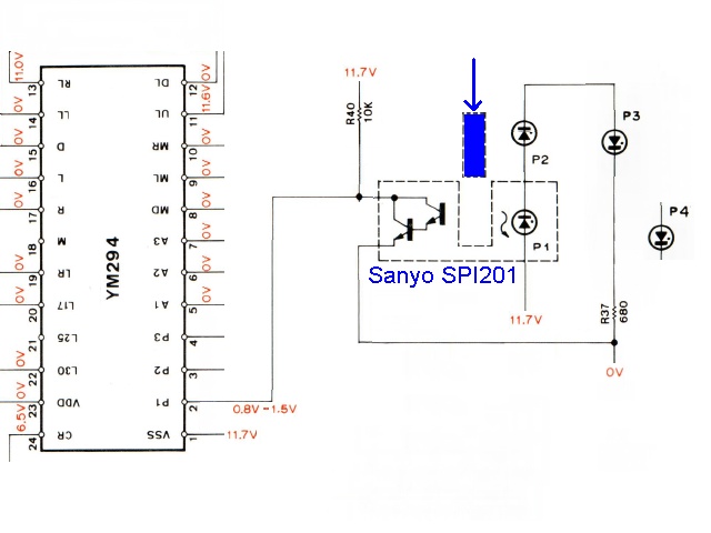 |
| Fig.49b, the simplified photogate circuit, pin P1 on the YM294 should measure between 0.8V and 1.5V if everything works |
Studying the circuit we note R37 to ground which regulates the current in the 3 LEDs in series (inside the 3 photogates).
R40 limits the current in the Darlington. When the transistor is illuminated by the LED it goes into conduction and we can assume a 1V drop across the double junction.
When the blue plate moves (the arm on the rails), it interrupts the light beam and the transistor switches off, the point P1 therefore rises to about 11V (not more of 12V or power supply is damaged!).
To test each photogate, we need to construct a simple circuit with a 12Vdc power supply, a 10K 1/2W R, and some flying leads. The R goes between pin 5 of fig.44 and the power supply, pin 2 goes to ground, we measure the voltage between pin 5 and ground. For other photogates the R goes on pin 4 and pin 3.
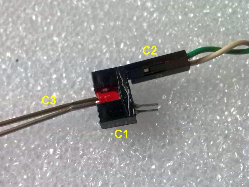 |
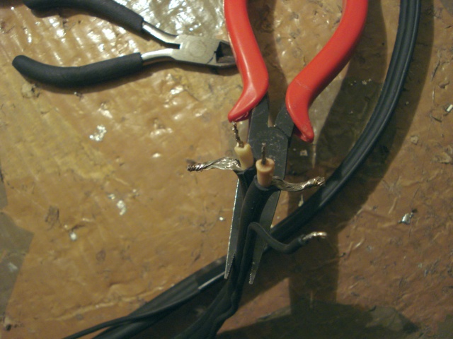
| Fig.49c, how to test a single photo-interrupter, we use a classic 3mm red LED retrieved from some device, we run from 5 mA to a maximum of 20 mA. C1= the photogate to be measured (here already desoldered), C2= wires to the measuring circuit, C3= the new LED and its circuit |
Given fig.49c, to test the Darlington transistor we measure between collector and ground, try 5 mA of LED current, then 10 and even 20 mA. With the LED switched off, with the photo covered by something to keep it dark (see C in fig.49) we should measure about 11V. Already with 5 mA the voltage should go down, if even with 20 mA and the LED with vivid red the voltage does not reach 1V then the Darlington is broken.
If, on the other hand, we vary the red LED current between 0 mA, 1 mA, 2 mA, 5 mA, 10 mA and 20 mA and see the collector voltage vary between 11V and 1V, then it is the SPI-201's LED that is 'finished'.
This time it is the LEDs that are degraded (although the dim red light can still be seen) as following fig. 49c the Darlington works fine.
 |
|
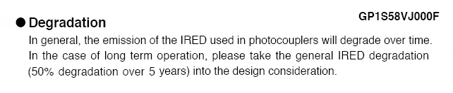
| Fig.49d, from the datasheet of the photo-interrupter Sharp GP1S58V we re-discover the degradation of the LEDs (5 years always on?) |
A replacement? This component was often used in the 1980s, e.g. also by the Sony STR-313L. Since the SPI-201 mounts a Darlington and it's a mini it's not easy to find, searching from page 998/1001 of the Farnel catalogue maybe something can be found, or ....
 |
|
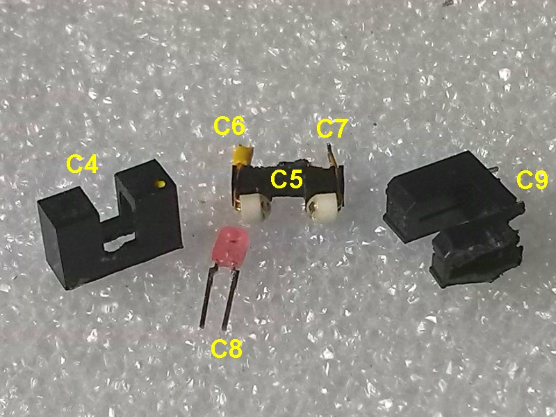
| Fig.49e, the disassembled SPI-201, C4= the housing, C5= the internal stand, C6= the original led, C7= the photo transistor, C8= the new led, C9= the disassembled GP1S58V led donor |
The C8 LED, however, is in infrared and we are not sure whether the sensitivity of the transistor, which is original to the SPI-201 that remains mounted, falls within the emission zone of the LED. Better to do some measurements.
 |
|
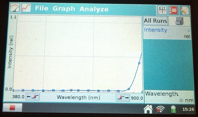
| Fig.49f, with a spectrometer we measure the emission of the LED with 10 mA of current. It is certainly in IR but our instrument can only see the side of the emission peak (large!), let's assume lambda of 950 nm |
All that remains is to mount the new LED and try it out. Referring to fig.49e, C5 is to be modified and C8 is to be fixed in C4 with black foam, the case is then fixed with appropriate glue. Once the glue has dried, the case can be soldered on.
 |
|
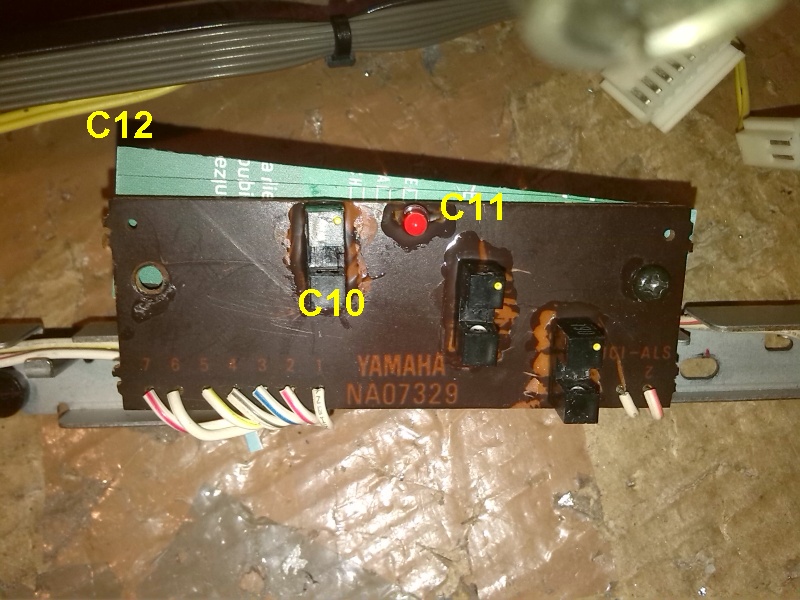
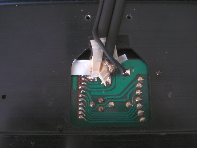
| Fig.49g, the PCB with the reconstructed sensors note the glue around the sensors (in this version they were also glued). C10= sensor rebuilt, C11= red LED added, C12= as usual, the PCB has to be raised with at least two cardboards! |
There are at least two reasons for the added LED in the PCB of fig. 49g, the first is to give an operating signal since the LED can be seen through the belts, the second is because the voltage drop of IR LEDs is much lower so the fourth LED (fig. 49b) allows the value of R37 to not change much.
 |
|
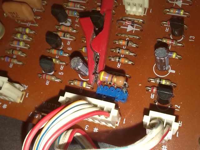
| Fig.49h, disassembling the mainboard each time to change R37s is not a good idea, let's mount a turret on which to solder the various test Rs |
We change the values soldered on the turret and find a value that gives current to the LEDs in series until we get about 1V on P1, P2, P3 of the YM294.
Let's repeat, the target is not the LED current but the V values of P1, P2, P3. If even reaching the forward voltage of the GP1S58V, 20mA, does not result in 1V or less on the YM294 then one, or all, of the Darlingtons are faulty, in which case ... best wishes.
Sensor alignment
Maybe the Slotted Optical Switches also work on Mr X's turntable but are not aligned. What do you mean aligned?
The PX-1 manual describes the sensors, photo-gate, with an explanatory drawing, below.
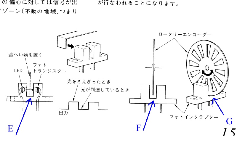 |
| Fig.50, if you look carefully at it in E and F, you can see how the position of the shutter/blade must be in order to permit at the gate to work properly. Even deeper is the position of the roller in G |
It is difficult to photograph the reciprocal position of blades - sensors, Let's see what can be done.
 |
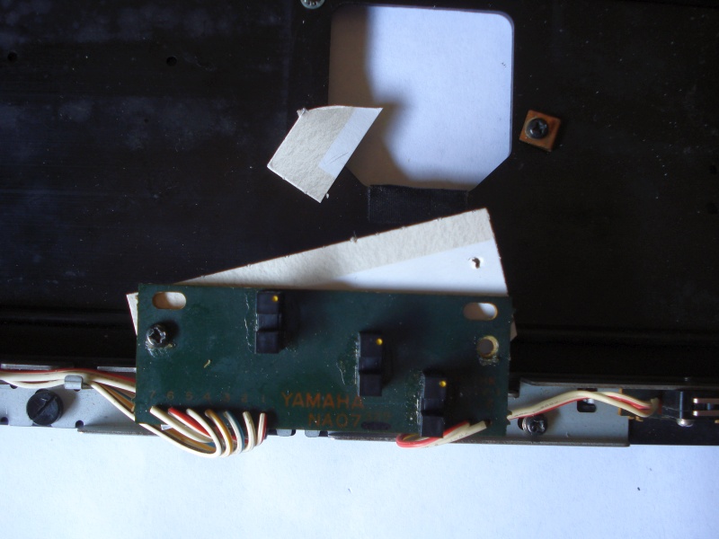
| Fig.51, BENT, the PCB holding the sensors is bent, it is actually its metal support that is crooked. The white block is a cube of Carrara marble that shows better the bend |
Nothing serious the sheet metal of the PCB holder bends by hand, but if it stayed like that the sensor towards the centre would never work. Sixth defect, diffcult to see.
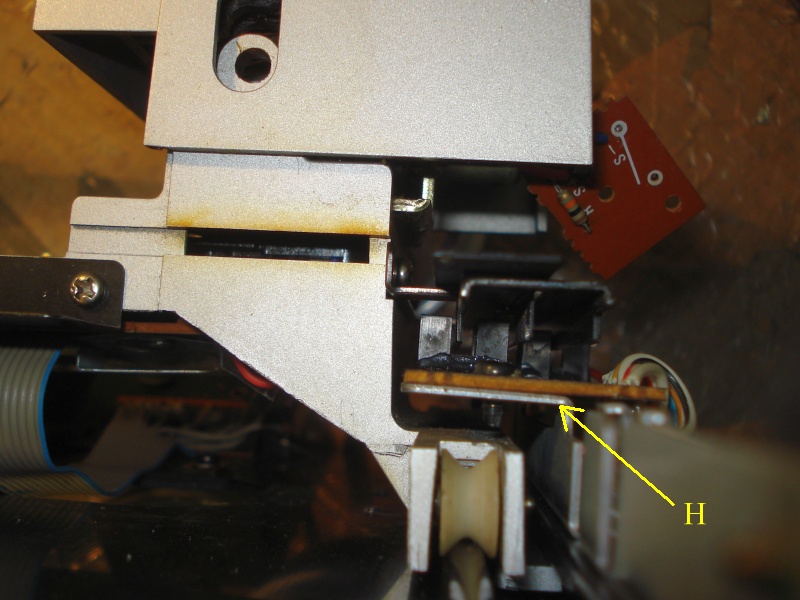 |
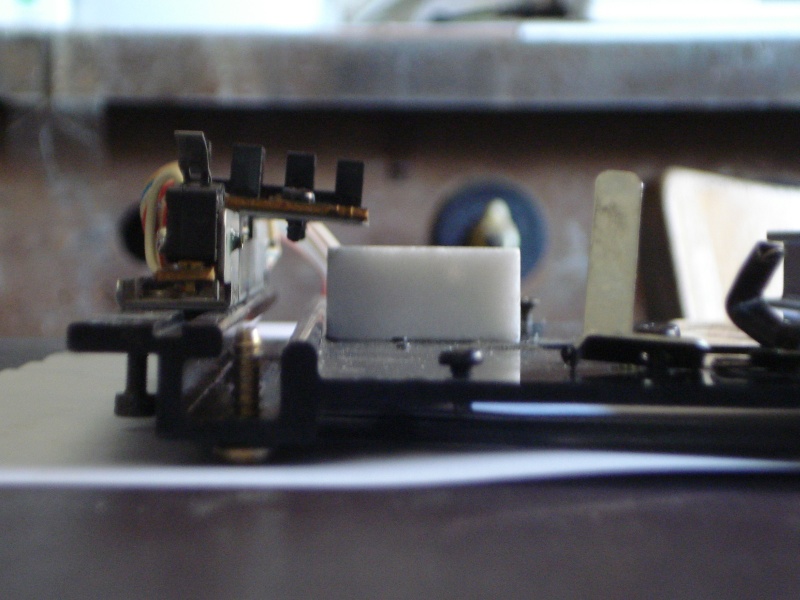
| Fig.52, we reassemble the arm and study the fold. H shows us that we have overcorrected the bend, it needs to be fixed. But we see another, bigger, problem |
We have to enlarge a section of the photo, lighten it up a bit and put a little eye on it to see this big problem.
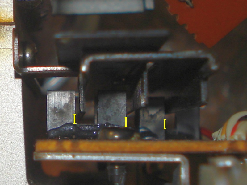 |
| Fig.53, the I gives us a reference on the depth of the sensor throat, the blade of the last sensor does not reach halfway, but how does it work? |
First we correct the bending well with many small attempts, then we solve the depth problem, the seventh defect, as shown in fig.50.
 |
| Fig.54, With a piece of cardboard, from a biscuit tin, we can raise the PCB by half a millimetre. In the end of work we used 2 cardboards |
Between folds and cards you have to do a lot of work aligning the sensors to the arm blades, sensors that seem NOT to be used just to position the descent.
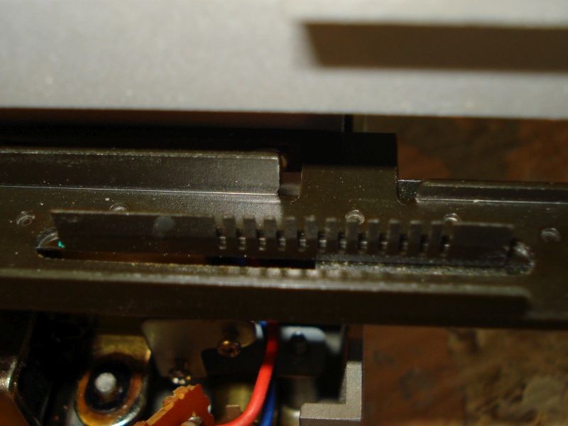 |
| Fig.55, one of the blades has a strange notched structure, as in G of fig.50, which looks like a tacheometer to detect the continuous movement of the arm ?? |
The mechanical alignment of the sensors is not mentioned in any service, nor is the existence of the toothing (fig. 55) described, nor its function.
As is often the case, those service manuals we have on the net are only a small part of what reached the service centres.
Many years ago I had a friend who ran a Revox service centre, and when I visited him I would often find him opening an archive drawers full of addenda, upgrades, recals, on a single tape reel model. He had five cabinet with drawers.
Unfortunately, many of the services on the Internet contain errors in diagrams, calibrations or, if you are lucky, tell you half the things you need (try to align the laser of the wonderful Kenwood DP-x9010 CD using the service, you will never succeed and you will do damage).
After all probably we have the 17, 25, 30 cm disc size switch working well, left/rigth arm stop working, one other step is done.
Limit switches
The tonearm has 2 end-stroke sensors that must be checked in the diagnostic process, they are simple mechanical limit switches and should give no problems, and then any multimeter will do!
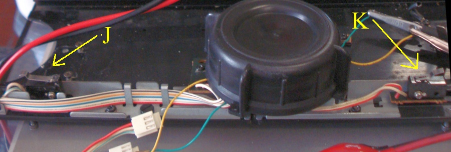 |
| Fig.56, the right limit switch J (S18) has double effect when left limit switch K (S17) has single effect Normaly Open (NO) |
The simplest method for testing is to check the closure, in ohms, of all 2 switches either by pressing them with a pencil or by sliding the arm.
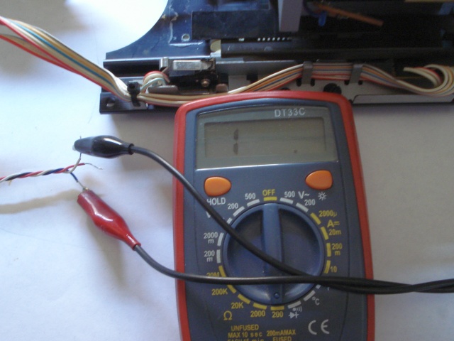 |
| Fig.57, test S18, the NO state, in fact shows an open state with almost infinite resistance between the contacts (on the 20Mohm range) |
By running the arm up to S18 the measured R-value should be about 0, let's try.
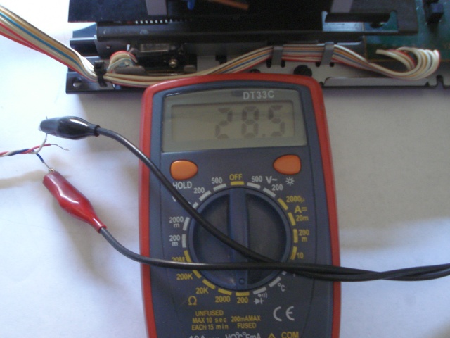 |
| Fig.58, Scrolling the arm asks for S18 but the resistance does not go to zero but remains too high 28ohm, we try pressing it with hand, same result |
The S18 switch needs to be changed, eigth defect, maybe the circuit only needs 28 ohms to realise it is closed, but any datasheet for such a thing mentions 0.1 or 10 ohms when closed.
Luckily S17 gives us 0.5 ohm closed, which between wires, flat cable and more is reasonable.
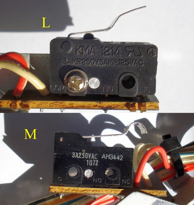 |
| Fig.59, the S17 switch, L, LMA 1214 3AMP250V works well and does not touch, S18 switch, M, AH3442 3A250VAC should be changed but the shape of the lever will give us problems |
Guess and riddle which one is missing? KMA1214 can be found in the Far East between 1.5 and 7 euros. No news of the AH3442, however. On searching, it turns out that it is a Matsushita, now Panasonic, and the closest to the catalogue is the AV3442 (not other codes mentioned by some fake seller).
On Mouser it would cost 1.35 euro but we have to wait 24 weeks!.
 |
| Fig.60, the replacement for AH3442, an Omron found in an electronics shop. A PET strip was glued under the lever as the fold on the lever was not high enough for a safe switch |
Trying again with the multimeter, in ohms, all NO and NC positions of the swicths now works.
Criminal Exploded View
To diagnose the function of the arm, an Exploded View would be of great help, but the one on page 21 of that fake service manual is, to say the least, criminal. It looks like it was designed by a child for a school assignment. It doesn't contain anything interesting, missing important parts and all the dismantle of the arm and bearings.
Have you ever seen an exploded view of a 1970 Alfa Romeo Giulia 1300 Super gearbox? Here is a scan of one page, this is en exploded view useful for those who need to get their hands on it.
Similar to ...
If during restoration we find some destroyed and irreplaceable part that cannot be built from scratch, it may be useful to know if there is a similar arm in Yamaha's production. At first glance it seems that the arm of the P-850 and P751 turntables have a similarity with the PX-2. The motor of the P-850 also bears a resemblance to that of the PX-3 (not the PX-2).
Unfortunately, the PX-1 bears no resemblance to any. As is always the case with the best.
Counterweight damping
Almost all tonearms for turntables have a similar structure with the counterweight decoupled from the arm tube, often with rings, tubes, or strip of rubber.
In the PX-2, the decoupling is provided by both a rubber layer and a rubber tube (but it is a single piece) into which runs the threaded pin that attaches the counterweight to the arm pivot.
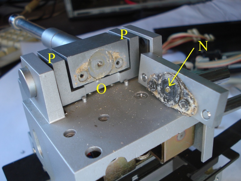 |
| Fig.61, the pathetic state of the rubber of the counterweight, did someone put glue on it? We see in N the threaded fixing stud, in O we cannot see the horizontal motion bearing, in P there should be the vertical motion bearings |
With the disassembled tonearm in fig. 61, we can gently test the "consistency" of the 3 bearings by hand. Try moving the arm in unusual directions, for example twisting the arm tube, to see if the bearings are loose, tight or correct. You have to have disassembled and rewired dozens of arms to tell if a bearing is right or wrong.
Finally good news, the bearings are solid and well tightened.
With horror imagine the case of having to dismantle the three bearings without an exploded view. Or just having to tighten probable needle screws without having the correct tightening torques in Newtons (or Kg), a nightmare.
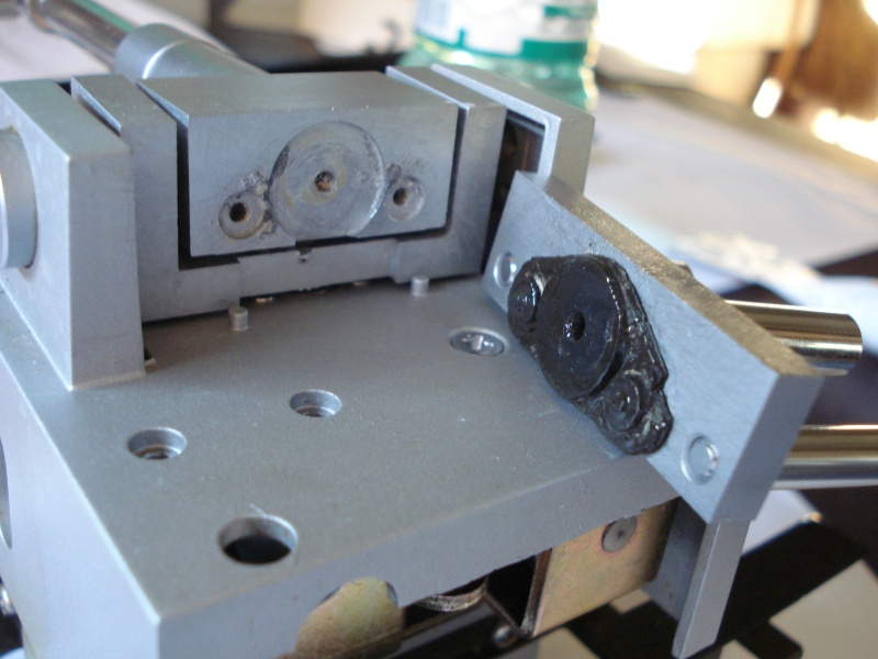 |
| Fig.62, the whole piece shown with N in fig.61 is boiled to soften rubber and glue. The rubber is removed from its seat, still clean and dipped in silicone oil, dried and reassembled |
In fig.62 you can see that a small piece of rubber broke off, it was too glued, but if we had not been able to restore the whole rubber's piece the end of the turntable was near (build the heavy doorstop). Ninth defect solved.
Cueing tonearm Up
What is expected of a tangential arm if the power fails while it is playing?
That the arm lifts up so as not to tear the cantilever (there is no longer control over the arm's movement, maybe it stays fixed). In a pivoted arm, on the other hand, the cartridge is dragged by the groove until the platter turns, as it did before the power went out.
Every manufacturer has found a way to solve the problem but I have seen 2 tangentials arm that do NOT solve it, amen for the stylus (I'm not mentioning names, I don't have money for lawyers, but real audiophiles know).
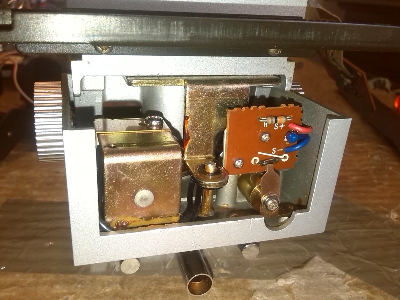 |
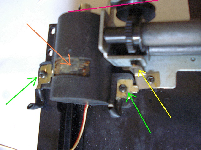
| Fig.63, Yamaha's solution, on the right the sensor that tells us if the arm is fully raised (should it be calibrated? on the service it says, nothing), on the left a solenoid that pulls the arm down |
We start again with diagnostics, does the S16 reed sensor work? does the magnet make it close? how many ohms? make and model?
Here we go again in the hell, damn exploded view, the block on the right of fig. 63 does NOT even exist, the wiring diagram mentions it as S16 and in the part list there is a "micro lead switch".
With a method similar to fig.40 et fig.44 we can, with an ohmmeter, test S16, NO as from the schematic and closed by approaching a strong magnet. It is broken remains Open.The tenth defect.
It's exhausting, another repairman who has to support his family with his work after hours and hours would have given up by now, everything you touch here has a problem, but when does it end?
 |
| Fig.64, someone has already put their hands on it given the state of the screws securing the entire block |
It seems simple to detach the sensor assembly, but this element is also the problematic up-and-down damper of the arm.
 |
| Fig.65, on the right the damping system on the left the anchorage with the short screws securing the circuit |
Since we had to dismantle the damping and end-positioning system (upwards) to change the reed relay, let's try to understand how it works.
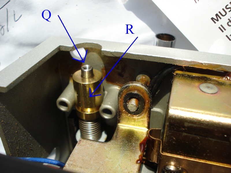 |
| Fig.66, the solenoid on the right pulls the arm downwards, when it is no longer energised the spring, you can see in the centre, pushes the arm upwards, sliding Q, which is braked by grease in R. The end-limit of Q is the screw of fig. 65 and the frame that with its magnet closes the reed |
Clearly, after years of use, or oblivion, the grease between Q and R in fig. 66 has hardened or been lost so that the descent (but worse the ascent) of the tonearm is compromised.
Unfortunately, this "calibration" is also NOT mentioned at all in the service manual and there is not even a reference to "what fluid" must be used.
Also, reaching the mechanism it is not easy as you can see from the photos.
A repair technician would probably ask you for 100 euros to disassemble everything, find the right fluid and reassemble with the risk of damaging the delicate Reed or frame with magnet.
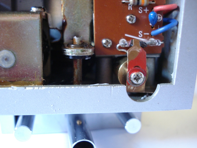 |
| Fig.67, the reed switch has been replaced, the original one was a sub-miniature 8mm long found in some catalogue but out-of-stock, the one fitted is a 12mm. The magnet is also correspondingly larger |
See in fig.67 to mount larger reed you can notice the gentle bending of the rheophores (delicate in both bending and welding), which do not go through the holes but use notches already present to reach the PCB from the top. Be careful not to touch the chassis, there is very little space.
Cueing tonearm Down
As already mentioned what happens if the power fails when the turntable is playing? In the PX-2 the arm is always UP and is pulled down by a solenoid, a similar mechanism is present in the Technics SL-QL1 tangential turntable.
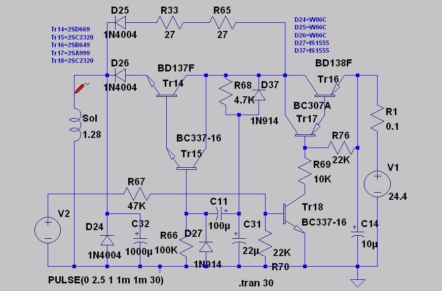
Since we find another disaster here, let us begin by studying the circuit diagram of the solenoid.
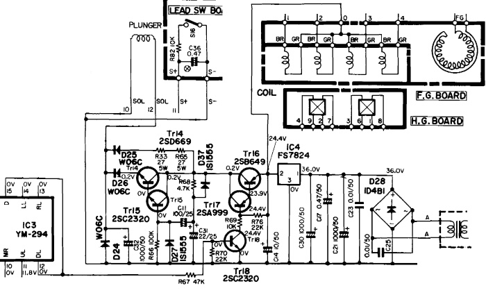 |
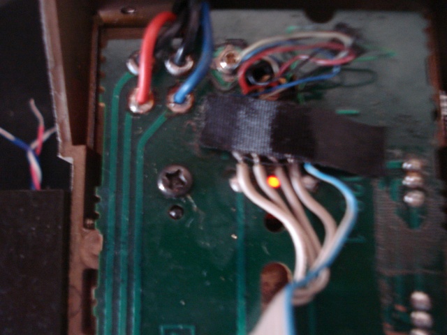
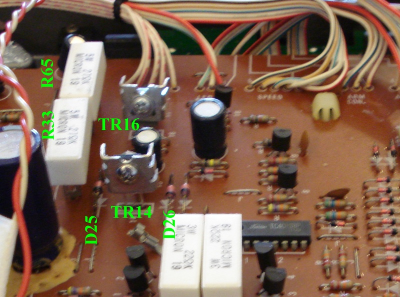
| Fig.68, extracted from the service here is the circuit diagram that drives the solenoid. Here is the enlarged photo |
With 2 thin wires we take contact no.10 (gnd) and no.12 (+) of the flat cable and connect them to the bench power supply.
IC4 is an LM7824 and produces a very strange output of 24.4V. Given the voltage drop of a conducting transistor, TR16, another transistor, TR14, and a diode, D26, the expected power supply should be 20V, free current. But perhaps the real power supply for the solenoid passes through D25.
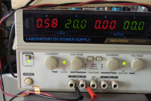 |
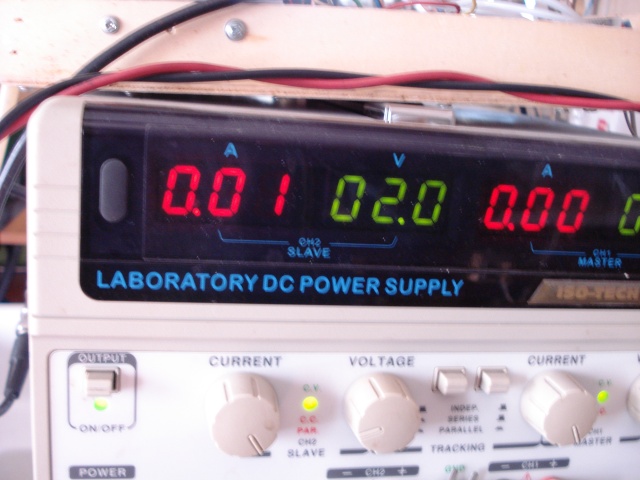
| Fig.69, at 20V the solenoid consumes 0.58A, i.e. it dissipates 11.7W, which is crazy, after 1 minute it will boil. Something is wrong |
That meager FS7824 has to run the whole left-hand circuit in fig.10, it has to turn the motor with great force and should also produce 0.58A for the solenoid and the rest of the circuit, it CANNOT there is something broken.
Having repaired the cueing-up sensor and damper as shown in fig.67, we use a ohmmeter (battery-powered) between pin 10 and pin 11 and do supply voltage, and remove, to the solenoid.
For this test you have to balance the arm so that there is about 2g of weight on the cartridge, just mount the headshell and adjust the counterweight.
FAULT, one other!
To remove the solenoid, you have to unsolder (on the wrong side of the PCB) two black wires and unscrew a Phillips screw. Remember to pass a "pilot" wire when you remove the 2 black wires.
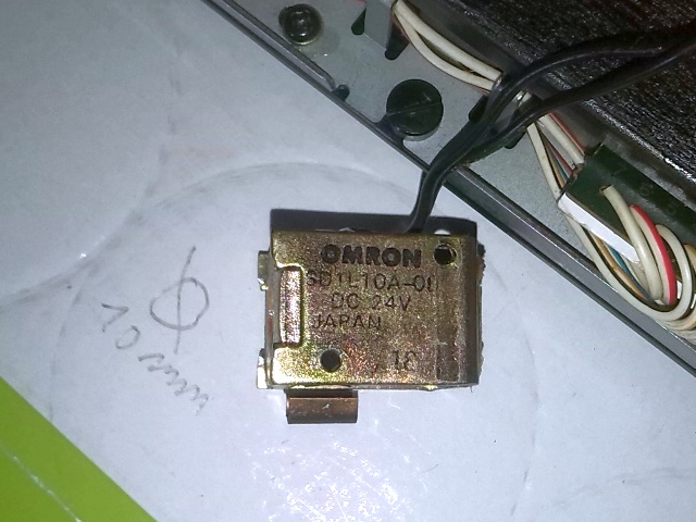 |
| Fig.70, Omron SD1L10A-0D, DC 24V, Japan, the solenoid is fixed with the screw under the Japan marking and with a chassi's pin in the other hole |
Nothing can be found of the SD1L10A-0D, only a datasheet from Omron year 1992 with similar solenoids. This one is strangely compact for a 24V and too low in resistance, about 35ohm.
After disassembling it, the solenoid seems to be "baked" and the plunger, when pushed by hand, resists but then gets stuck and the spring fails to pop it out. This is why the arm does not lift up when the voltage is removed. The eleventh defect.
The Solenoid Enigma
The solenoid looks original, no one has disassembled or tampered with it.
If you try the plunger again and look carefully, you find that the coil former is deformed by the heat, it is no longer round and the plunger sticks.
The solenoid has to be unwound, a new theoretical 10 mm coil former found (i.e. 10.2 mm) and rewound. I have asked three transformer's man but they won't do it, it would cost too much, and according to them there is something wrong with the calculations.
If the spare part cannot be found, the turntable is dead.
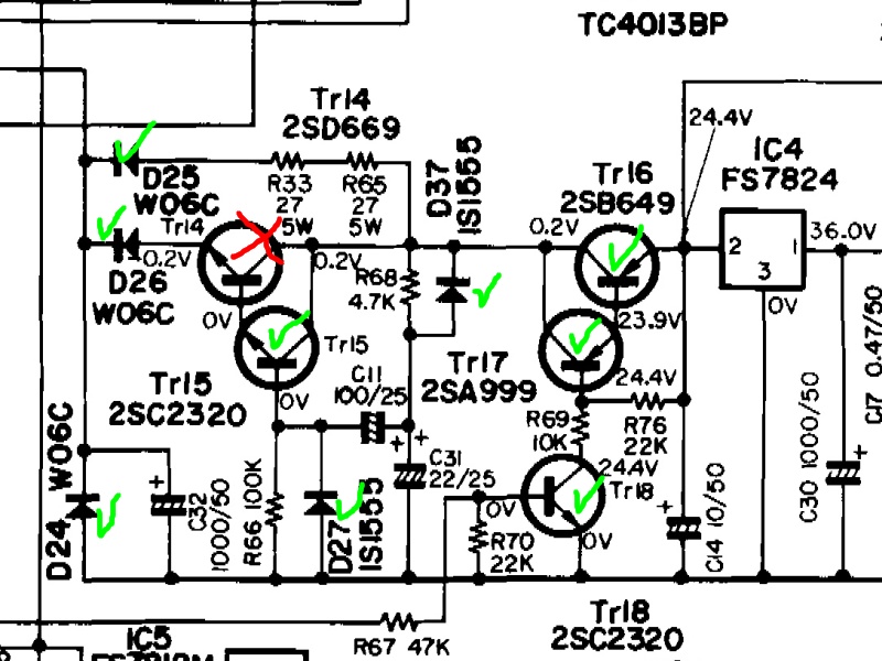 |
| Fig.71, By testing all the active components of the section driving the solenoid, we can find out why the solenoid has cooked. Transistor 2SD669 shows a short between the Collector and Emitter, i.e. current is always flowing to the solenoid, this transistor has NO equivalent but is easily found in electronics shops |
Almost all components can be tested without disassembling them, all you need is a Hameg oscilloscope (or a few Hitachi, HTC, BK Precision) and a little experience in recognising shapes perhaps distorted by a capacitor in parallel. If you only have a classic oscilloscope, a good buy is the Hameg/Rohde & Schwarz Component Tester HZ65-3. Or given its schematic and a small transformer we can build one with even more selections on (low) currents and voltages.
If we change the 2SD699 (TR14) and the twelfth defect is also solved, but the problem of the solenoid remains.
 |
| Fig.72, by changing the 2SD699 we add on TR14 and TR16 a small heatsink |
When a component as simple as a coil gets damaged before replacing it, you have to find out what happened or the new one will do the same.
Unfortunately, we first have to study the open frame solenoids and then the Yamaha circuit.
All this study on a component that looks stupid, reading dozens of datasheets, studying other circuits and then simulating the Yamaha circuit takes hours and hours that an honest repairman must count in the eleventh defect.
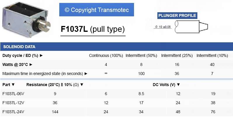 |
| Fig.73, a solenoid with a plunger identical to ours but with the frame size too large. In the text below we study the characteristics |
Fig.73 comes from a Transmotec datasheet, which is very comprehensive and allows us to understand how a solenoid works.
Let us define some parameters, without giving a lecture on electromechanics:
From what we have seen so far, our solenoid looks like a 12V working with %ED of 25% ? But labelled 24V ?
Searching and looking for a replacement for the Omron solenoid, one can find the TDS10A but it is too long, or the TDS-10G (pag.17 of the datasheet) with frame similar but it has a bit too many ohms.
However, it is confirmed again and again that the Omron is a 12V working with a %ED of 25%.
Pull-type solenoids have an interesting feature, at first the coil is almost wound in air, low inductance, with the plunger inserted the coil is wound on a ferromagnetic core, high inductance. Surely the non-idiotic Yamaha designers were aware of this effect, given the complex circuitry of fig.68.
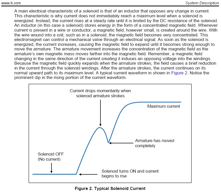 |
| Fig.74, figure taken from a Texas Instrument application note. From the description and the figure, one can better understand how to drive a solenoid like ours that should not be able to work |
I.e. one could use a high initial voltage, wait until the plunger has run its course, and now that the coil has a much higher inductance, lower the voltage (and of course the current) to maintain the pull on the plunger itself.
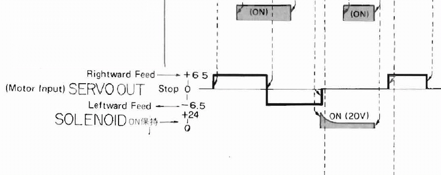 |
| Fig.75, in cutting out so much information, sometimes a piece of information escapes the manufacturers and remains in the service manual. It mentions 24V for the solenoid but also shows the shape of the applied voltage, which starts at 20V and goes down to ? (the answer at pag.8 of PX-3 s.m.). At what times? More reading this data the motor of fig.35 is a 6Vdc |
In order to save the turntable, we have to rebuild the solenoid by finding a new shell and rewinding the coil. But it will be similar but not the same as the original, so you need to study the circuit, simulate it, to see if any values need to be modified to suit the new solenoid.
LTspice has become one of the most popular simulators, meanwhile we design the circuit.
 |
| Fig.76, you cannot find 'models' for Spice of the transistors used by Yamaha so you have to find an equivalent that is included in LTspice by looking similitude on features and not shape |
There are various groups and blogs that strive to add transistors, fets, diodes, to LTspice's original (too short) list, but the quality of the models is often questioned.
If we really need, for example, a certain jFET, it is better to search for the model of the same component on several forums (often a copy of the copy) and find a few different ones and compare them.
Having settled the model issue, let us try to simulate the operation of the circuit. Plausible values must also be entered for the solenoid by taking them from various data-sheets.
In this file, LTspice-Yamaha-PX2-solenoid-(plus-models).ZIP, the LTspice simulation of circuit show in fig.76 and also my models for Byt (standard.bjt) and Diodes (standard.dio). ABSOLUTELY NO WARRANTY ON THE QUALITY AND OPERATION OF THE MODELS, USE THEM AT YOUR OWN RISK OR RATHER DON'T USE THEM.
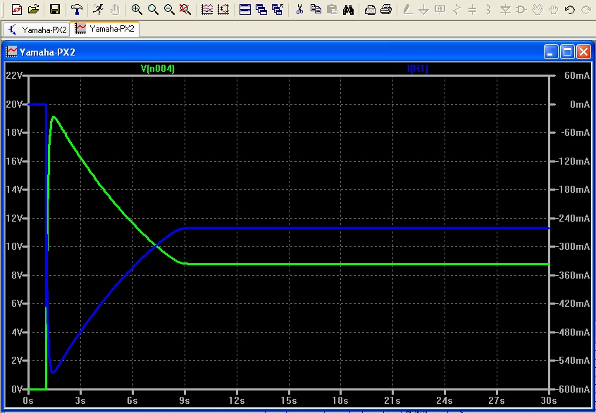 |
| Fig.77, we note the probe in fig.76, from the simulation we obtain this voltage on the solenoid, the current reaches a peak near 500mA after about 1.5 second and then slowly drops to about 250mA. We note that R1 has been added to the circuit, which is irrelevant but necessary for measuring the total current |
The shape looks very much like fig.75, maybe we were good at simulating the circuit. The maintaing curve is interesting, an design error here after minutes and minutes with this current can warm the solenoid.
Now that we have a working simulation, we can change a few values and better understand the circuit, which we will need if our rewound solenoid is not "identical".
By changing a few values we obtain: (at pulse) , (steady state)
New coil for Solenoid
First the solenoid must be removed from the arm, the C-frame must be carefully disassembled, separating the coil from the frame.
Before rewinding, the copper wire must be carefully measured (diameter with lacquerel 0.21mm or 0.22mm), and if possible the number of turns must be counted.
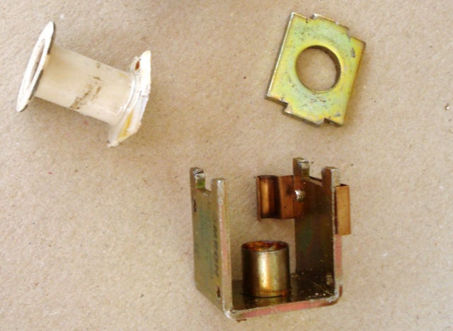 |
| Fig.78, the disassembled solenoid, you can see the heat-deformed coil former that blocking the pin |
It would be much better to recover all the copper wire by rewinding it onto another spool and find a new coil-former then rewinding the same wire.
Never do this with high voltage coils, with our 24V coil you could try but the wire seemed "cooked" so we bought an expensive new spool.
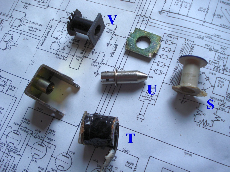 |
| Fig.79, old and new parts for the solenoid, S=the old coil, U=the 10mm plunger that must slide easily into the former, T=a first coil but not perfect, V=new coil former recovered from .... |
The first attempt to rewind the coil, T in fig.79, does not work. The copper wire must be laid in tightly tightened layers that are solid with each other even without sealing varnish. The tight coils deform the thin spools a little so the pin does not slide as it should, let's try again.
We see V in fig.79, a spool recovered from a high-frequency transformer of a 150W switching power supply. With a little cutting and sewing, we obtain the appropriate coil former.
 |
| Fig.80, a superb super-automatic digital reel spooling machine equipped with artificial intelligence with continuous resistance and inductance measurement |
We have to ask a friend who rewinds a bit of everything, for fun and not to throw things away (the last one a washing machine pump with 2 rectangular reels). He sets up a kind of spooling machine that with a few tricks of the trade provides us with an almost perfect solenoid this time.
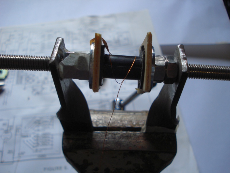
Having rewound the solenoid we have also solved the thirteenth defect, all that remains is to test its operation.
 |
| Fig.81, here is the rebuilt solenoid, the pin runs 'loose' and the coil almost fills the frame. A little problem is closing the frame, but it is made of soft iron and is soldered with tin/lead |
We re-solder the original black wires and secure the solenoid with the single Phillips screw. Before reassembling the arm we take a few measurements.
 |
| Fig.82, the mounted solenoid, 34.4 ohm, 14.4 mH. Slightly more then original 30.3 ohm, 12.7 mH from one other working tonearm |
The original machine-made coils were certainly tighter (or the wire was a little thinner and longer), we will have to tweak the control circuit. Let's do some measurements with an external power supply.
| Tab.2, current vs voltage for the new solenoid | |||
| meas. n. | voltage (V) | current (A) | watt (W) |
| I | 18.5 | 0.51 | 9.44 |
| II | 17.1 | 0.47 | 8.04 |
| III | 15.0 | 0.40 | 6.0 |
| IV | 10.0 | 0.27 | 2.7 |
| V | 8.0 | 0.22 | 1.76 |
| VI | 7.0 | 0.19 | 1.33 |
With measure no.1 the arm drops readily, reducing the voltage up to measure no.4 the arm stays down. With measurement no.5 there is some uncertainty, measurement no.6 cannot hold it and it rises quickly (with about 1.5 grams of weight on the cartridge).
 |
| Fig.83, another modification, a thin sheet of wood shown by the green arrows |
The Slotted Optical Switches should be protected from ambient light with something better than the original plastic pieces.
Tonearm cable
With reference to fig. 13, the phono cable must now be re-soldered, avoiding false contacts due to the small space available.
 |
| Fig.84, the excellent phono cable used by the PX-2, Neglex 2496 interconnection cable, 2710 AWM Vw-1 Mogami |
By reading the measurements on the cable shown on the Mogami website, we can make some measurements on the cable alone and afterwards connected to the tonearm.
The Mogami catalogue is a huge source of information that many audiophiles overlook or don't know at all, maybe start reading from page 74 onwards.
As per fig.84 this is a dual coaxial cable. For each channel it has a center wire (L wire), an insulator, a series of braided wires (L shield), an insulator, and an additional wire for turntable ground (gnd).
Having five conductors we measure one versus all the others (not just the capacitance to shield). To simplify, we do not measure all possible inductances.
| Tab.3, capacitance of Neglex 2496 cable alone, with original RCAs | |||||
| picofarad (pf) | L wire | L shield | R wire | R shield | ground |
| L wire | 105 | 33 | 50 | 31 | |
| L shield | 100 | 46 | 90 | 43 | |
| R wire | 33 | 49 | 102 | 43 | |
| R shield | 46 | 90 | 98 | 70 | |
| gnd wire | 30 | 44 | 41 | 70 | |
Usually only the capacitance of the conductor versus the screen, sky cells of tab.3, is measured, but all other capacitances are also important, perhaps more so!
 |
| Fig.85, after soldering we insulate the conductors with small pieces of polyethylene |
Having soldered the phono cable, fig.85, we mount the headsheel to measure the capacitance as the cartridge sees it, starting with its colored wires.
| Tab.4, capacitance as see the cartridge using original phono cable and RCA | |||||
| picofarad (pf) | L wire | L shield | R wire | R shield | ground |
| L wire | 0.17 | 131 | 52 | 73 | 72 |
| L shield | 125 | 0.28 | 75 | 130 | 109 |
| R wire | 51 | 75 | 0.20 | 124 | 79 |
| R shield | 75 | 131 | 130 | 0.41 | 146 |
| gnd wire | 73 | 108 | 85 | 149 | 1.11 |
Really interesting results that silence a thousand chatters and perhaps dismantle some certainties (try it with your astronomical and overpriced arm, the little instrument in fig.82 is enough to disturb granitic certainties).
The plate have a pin
Often there is no need to reinvent the wheel, just take a similar-but-different, well-functioning object and adapt its technology to our needs. The platter of a direct-drive turntable is not much different from the one pictured below. It too has servo controls to keep the speed constant!
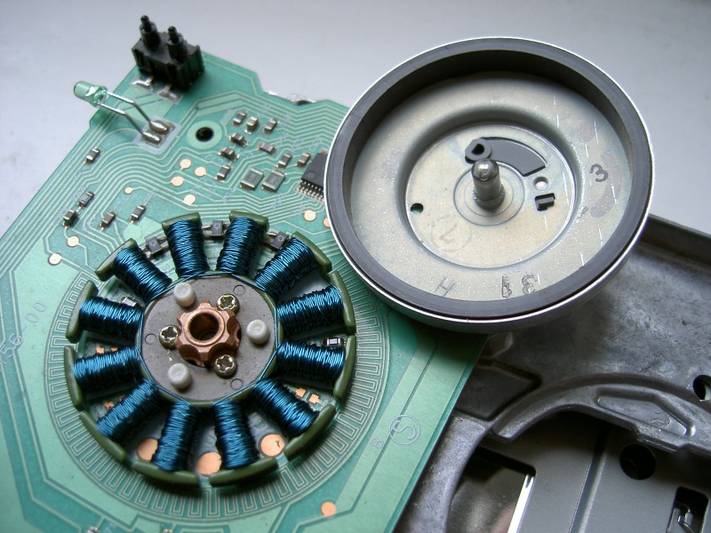 |
| Fig.86, from Wikipedia, the motor from a 3.5 in floppy disk drive (by TEAC Corp.). The coils, arranged radially, are made from copper wire coated with blue insulation. The rotor (upper right) has been removed and turned upside-down. The grey ring inside its cup is a permanent magnet. This particular motor is an outrunner, with the stator inside the rotor. The pin looks like a ball-bearing spindle but it's just well-rounded. The Hall sensors are included on the board, between coils, in the upper left (thank to Sebastian Koppehel) |
Certainly after 40 years of rotation, or sitting on the shelf, the pivot oil will need to be replaced, there will be the "ball" on which the pivot rests (or any other thrust bearing system) to be checked, the bushings/bearings/rings that hold the pivot in place are to be checked.
But disassembling this motor is a hard work, already getting it out of the frame is a lot of work. Once on the table it seems to be closed by rivets, no, no, they are for something else. Once disassembled it's a beautiful sight (here an exploded view of the PX-1 motor), a construction worthy of its name with some doubt about the pivot.
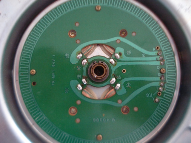 |
| Fig.87, see the motor coils and centre pivot, note the soldering on the right side of the photo, before closing it up better to remove the old tin and resolder |
Repair the fourteenth defect, after the maintenance is over, the engine chassis runs a wonder, you can only feel a little magnetic brake (if we turn it by hand, it's a dynamo!).
Given the pivot 2Kg clamps are NOT to be recommended, NOR with 1Kg clamps, maybe 400 or max 500 grams are welcome (I love the Oracle Delphi clamp, so effective and so light, but 400 euros is a crazy price).
Visual inspection
Before switching on any equipment, a visual inspection is a must. Probably no damage can be seen, but if there is already "visible" damage, action must be taken.
A power-up procedure with various precautions is described on the Quad II page.
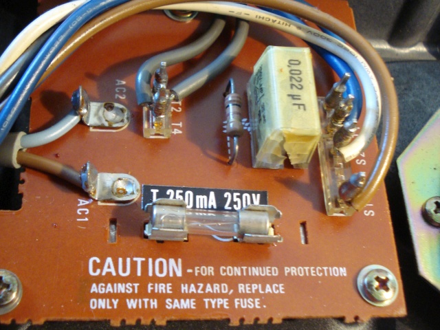 |
| Fig.88, C4 of the fuse board appears to have been exploded, we did well to make a visual inspection |
The C4 capacitor did its job but after 40 years it left us, it must be replaced with an identical one, they are called Spark Killer Capacitor.
Having replaced the capacitor with one suitable for the voltage of 250Vac, we also solved the fifteenth defect.
We continue with the visual inspection, take apart everything we can, and here are some more surprises
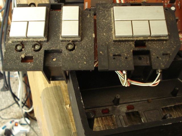 |
| Fig.89, disassembling all the switch's PCBs one finds this, the original photo is horrifying |
You have to disassemble the buttons, clean the contacts (don't scratch off the gold plating!), reassemble them and test them one by one with the tester, then reinstall the PCBs.
Once all contacts have been cleaned up, even the sixteenth defect seems to have been resolved. The patience is almost over, we can't take it anymore.
Build cables and circuit
As well described in the service NEVER run the motor without the heavy platter, for this the turntable must be placed flat on 4 supports and measurements and calibration can be started (with a short screwdriver reaching the trimpots).
And having to fetch the signals from various test-points (some we add ourselves) you have to build some cables and circuits.
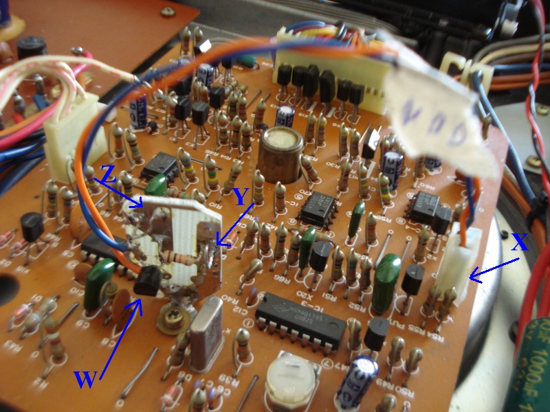 |
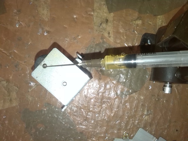
| Fig.90, with a small PCB board you can build the buffer circuit, let's see W= the JFet, X= the connector on the test points with a bit of cable, Y= the link for the oscilloscope probe ground with the track ending on the support screw, Z= the link for the probe |
The service manual, although not very clear, describes for the first step of the setting the construction of a small circuit (Fig.2 of page 6), with a JFet acting as a buffer for the output signal from an integrated circuit.
Have you ever seen one of those gurus pontificating their prowess show off said little circuit?.
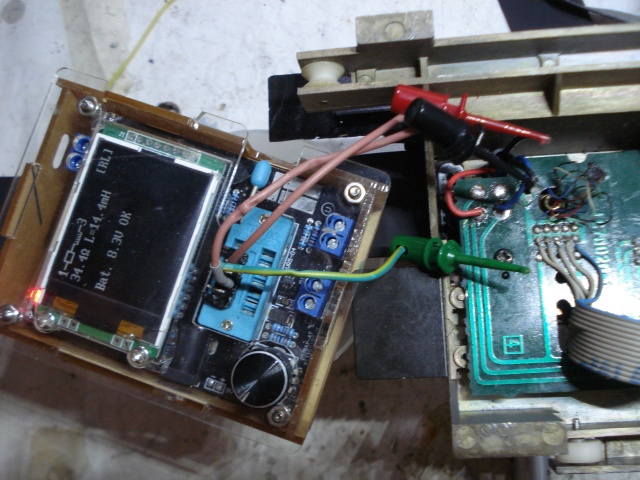
Motor setting
Build the circuit we can measure voltage on 10K and set the quartz synchronization.
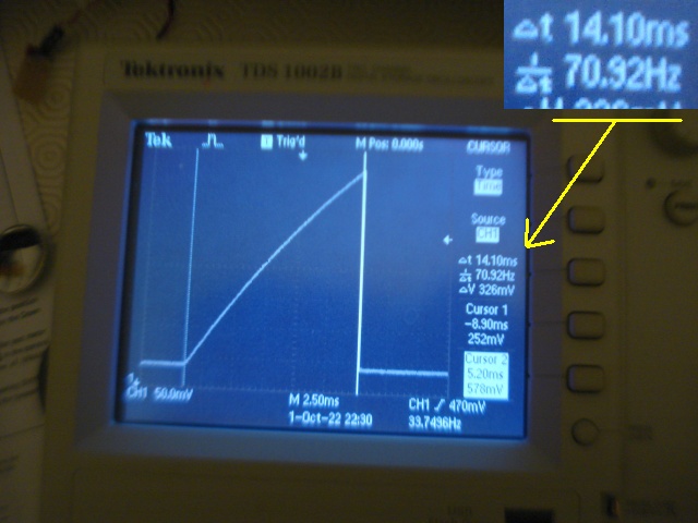 |
| Fig.91, with a digital oscilloscope you can measure the signals while watching the waveform, and with the VR1 trimmer you adjust the time for about 14ms |
Tonearm angle adjustmen
The tangezial arm MUST by its very nature be tangent to a circumference drawn by the groove impressed in the vinyl.
Fig.3 and fig.4 on page 6 of the service manual explain well the concept of tangential and how to measure it. Let's start with the arm in UP position.
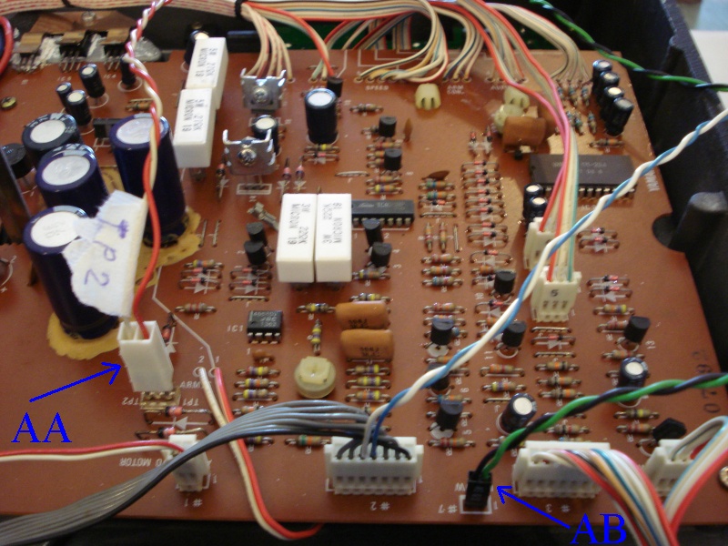 |
| Fig.92, we build 2 jumper cables, AA= for test points TP1-TP2, AB= an undocumented function that simulates the UP position of the arm if the 2 pins are closed (you have to solder 2 pins in the existing pads) |
The centre in the UP position is easy to maintain, the arm fits into a fork (adjustable) that keeps it in the centre.
Now, simply measure the voltage between TP1 and TP2 with a good multimeter and adjust VR2 for the value closest to zero..
 |
| Fig.94, important that the turntable is level using a spirit level (a little blurry here). The adjustment at the end is very good |
For the DOWN position there are difficulties, you cannot rest the arm on the platter, it spinning all the time! The manual suggests a shim equal to the height of the platter + mat, which also serves to hold the arm in place.
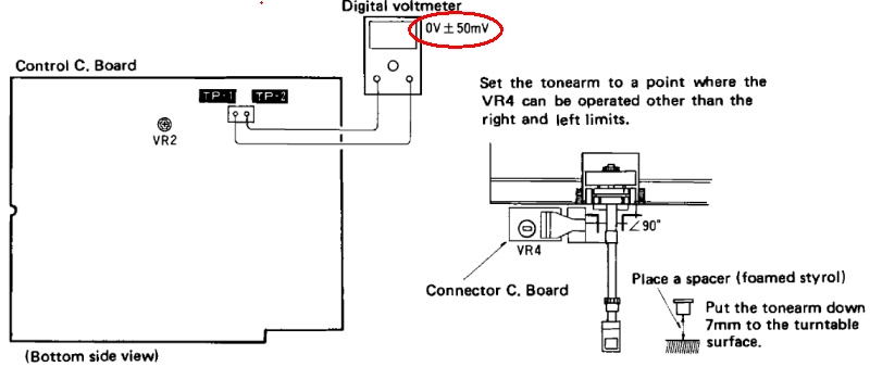 |
| Fig.95, a drawing with some errors, 7 mm is just not enough, VR4 is unreachable in any position |
To make the calibration we have to make a hole in the chassis over the VR4 trimmer. It is really important to maintain the 90 degree angle as described in fig.95 always with the turntable well level..
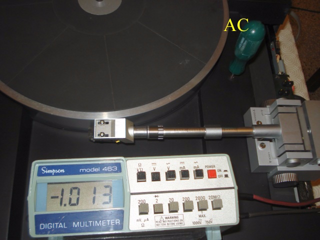 |
| Fig.96, we see in AC the screwdriver going through the hole just made and reaching VR4. The foam under the cartridge has been removed in order to move the arm, in down position, and look for a 0.0V value. Unreachable! If you move the arm to 89 degrees it moves looking for the it's set-up |
A disaster, more than a tangential, and we are at seventeen defect. Let's see if the service and its designs help us. NO.
 |
| Fig.97, from the Japanese service some drawings of the tonearm, best realised |
You can see some kind of plate separating the LED from the 2 CDS and which seems to be in solidarity with the arm.
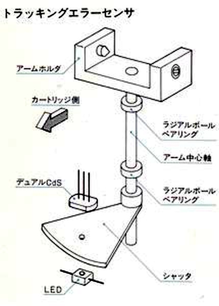 |
| Fig.98, also from the Japanese service, a drawing on the operation of the LED-CDS unit tracking the groove |
We understand that the perforated plate between the LED and the CDS is attached somehow to the pivot pin, perhaps the position can be adjusted. But there is no mention in any manual about calibrating the position of this hole, let's see if we are better than the fake manuals designer.
 |
| Fig.99, but then there is an UNDOCUMENTED screw to centre the hole in front of the LED |
Difficult to photograph, very hard to reach, with a very thin head cut and "little" travel. With several attempts, tilting the turntable, turning the screw, putting everything back on level you get an acceptable value.
Or you have to disassemble the whole arm pivot and move a fixing bushing that you can see with a good torch.
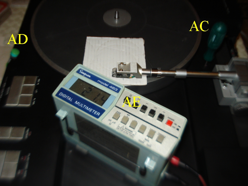 |
| Fig.100, tonearm in down position for 90 degree calibration, AC= the screwdriver on VR4 in the hole on the chassis, AD= another UNDOCUMENTED point to which a button can be added to stop the plate, AE= 21.4 mV are inside the red circle in figure 95 |
30, 25 or 17cm disc? Adjustmen
This setting is easy if careful restoration has been done to the Slotted Optical Switches as described from fig.43 up to fig.55 .
With reference to fig. 83, simply loosen the two fixing screws of the carriage and move it to centre just the beginning of the 30cm discs. The other disc measure are fixed.
Adjustmen of auto-up at the end of disc
Perhaps the comb grooves in fig. 55 are there to tell the Logic when the arm is moving too fast, i.e. at the end of the disc.
The manual suggests that we fetch the signal from pin 24 of IC3, a MADNESS, if you short something with the probe here you have killed an UNAVAILABLE integrated and once again the turntable is dead. DO NOT, DO NOT.
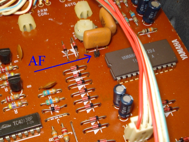 |
| Fig.101, a pin added with a hole on the PCB and a solder on the track that picks up the signal from pin 24 of controller IC |
With the added pin now just build a bipolar cable with red on this pin and black on a ground screw, then you need the usual digital oscilloscope!
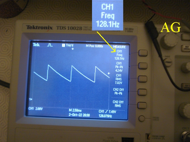 |
| Fig.102, with VR3 you adjust the frequency to 128Hz, the trimmer is very sensitive, but here's the result . AG= the cable cited above |
Figure 6 of the service manual also shows a sawtooth with the reference voltages to be obtained.
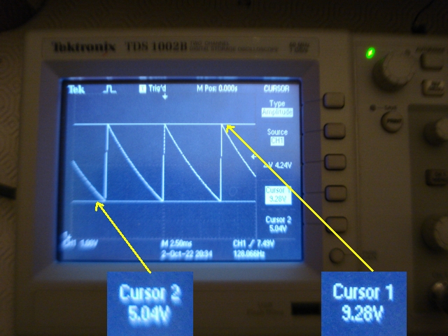 |
| Fig.103, the values obtained are really good for electronics that are more than 30 years old |
Tonearm driving speed adj.
The last setting is the sliding speed, manual, of the arm. It doesn't seem very important, but if we get the values in fig.8 of the manual we are sure that the circuits are working properly .
No photos this time the test has already been done by restoring the operation of the arm driving motor, fig.34 to fig.37.
We should note that already there is a hole on the frame, mentioned by the manual, since VR1 is also unreachable! In fig.96 we made another one, we have to find a black rubber bush.
Fit cartridge to headshell, easy
NEVER BUY A YAMAHA PX-nn TURNTABLE WITHOUT THE CARTRIDGE SETTING GAUGE, the gray parts on the right in Fig.2. I won't tell you how much he paid this disaster.
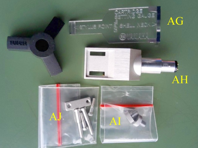 |
| Fig.104, pictured (from the Internet, by an audiophile, expert, seller) are all the important accessory parts for the PX-2: AG= the plastic template for positioning the cartridge, AH= the second headshell, AI= the additional counterweights, AJ= the aluminium screws and bar. WITHOUT "AG" DON'T BUY IT. Use mouse hover to see the enlarged photo of AG the gauge |
By following the user manual it is very easy to position the cartridge, without the template it is a titanic task, with the risk of damaging a Van den Hul or a Lyra that costs more than the turntable.
Having bought a Yamaha PX-2 or PX-3 without the W gauge in fig.104 is like the eighteenth defect. Something as easy as aligning the cartridge becomes quite a problem.
Alternative fit cartridge to headshell
If you don't have the CARTRIDGE SETTING GAUGE you have wasted money, but maybe there is a chance of salvation.
 |
| Fig.105, the white plastic is a typical headshell holder, the green line was drawn exactly 50.00mm from the headshell retainer (which mounts the rubber gasket) |
How to make the mark at exactly 50.00mm, not 50.9mm, not 49.2mm is a problem, maybe a good mechanical lathe operator would know how to do it.
Alternatively, you can rebuild the template with a 3D printer, there are many young enthusiasts in your town who have opened a FabLab, but WE NEED THE ORIGINAL to digitise it.
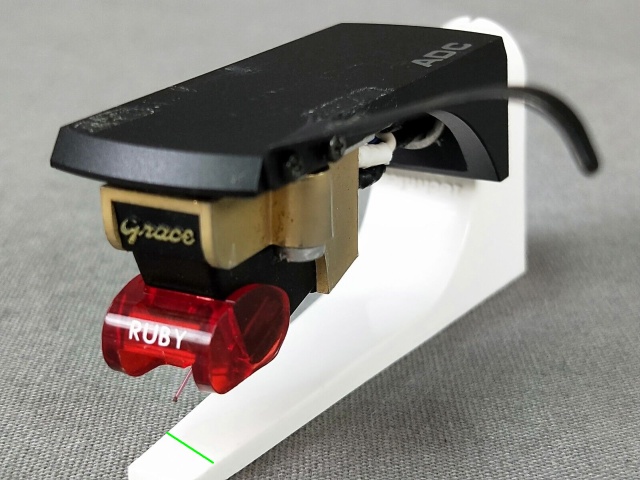
Yes the Fig.105 is a Chimera, the Grace F14-Ruby.
Fit cartridge in any tangential arm
Of course there is one method that can be used on ALL tangential arms, in fact there are 3:
The first one although very simple is almost never applicable, the arm does not move all the way to the pivot, and if we get the VTA completely wrong it distorts the measurement.
The second method is also suggested in the PX-1 manual, let's see it. For the last do you must have the "template" (or do not buy the turntable).
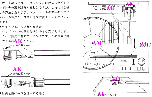 |
| Fig.106, from the PX-1 user manual, alternative methods for aligning the cartridge, can be seen better in the enlarged drawing, in the text below the instructions |
Once a perfect alignment has been achieved, the weight must be reweighed to the cartridge, but perhaps it was unnecessary to write that down.
All methods should be equivalent, but the one in Fig.106 also checks all arm mechanics.
Really fit cartridge with last method
Not having the PX-1 board we need an equivalent template, here we use a famous polycarbonate disc with various designs for aligning 9, 10 and 12 inch "pivot" arms, overang settings, and masks for calibrating tangentials, it's called ...... (but with what I paid for it why should I advertise it?).
Before remove the platter mat, adjust the cartridge's weight and VTA, put the white disc and fix it.
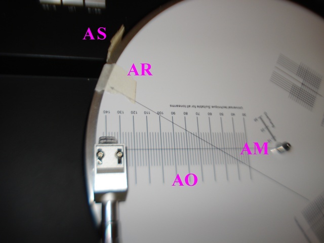 |
| Fig.107, we see AM= the radius on which the arm must travel, AO= the lines which must always be parallel to the arm tube, AS= a wooden wedge to keep the platter from spinning (after using the AD button in fig. 100 to switch off the motor), AR= three pieces of paper tape to fix the disc with the drawing to plate |
By raising and lowering the arm and moving it slowly on the AM radius, the stylus must remain on the line. But you must stop run of platter motor before fit the AS wood piece, yes there is an undocumented method (push the S18 of fig.59 stop the motor but also the tonearm!).
Or you move the stylus on the shell and start again.
Tonearm effective mass
And once again the Gurus, the Shamans, the Certainty-builders, the Infallibles explain to us poor cretins what the effective mass of the tonearm is and dictate to us which cartridge to buy (or we are imbeciles that will be insulted on the various forums and blogs).
Dear ignorant beasts, here we have a variable mass arm, you just have to figure out how to use it, but for you distributors-of-truth it is too much.
As this is a roadmap to the Yamaha PX-1.7 we discuss it in the upgrade.
How much does this cost?
At the end of the restoration, one must first take into account the cost of spare parts, the cost of the "service" that was required (to rewind a transformer or rebuild a PCB for example), and certainly one must gradually take into account the hours spent.
True art restorers add a cost for experience, i.e. for that thing that makes you polish a piece of wood artwork with shellac in less time (saving hours) and with a flawless "polish".
With eighteenth defect, some of which would have killed the turntable, counting all the above, a real repair shop, if it can get this far, should charge 1500 euros. And if he's honest, he'll explain that he'll always be there for you for future breakdowns, but he CANNOT give warranties on such a complicated piece of equipment over 30 years old!
An example of the cost of these restorations is the one provided for the JVC-Victor TT-801. A long page in Japanese describes the repair and also gives us the costs, in October 2016, 65000 jen, or today more then 500 euro. We note in figure C332 one of the nightmares of any repairman, one defective weld in 1000..
Repairing HiFi is not my main job. I have a full-time job, in fact I have two. Since I don't depend on repairs for my regular income, I can enjoy wasting time on restorations whose commercial cost would far exceed the valuation of the equipment itself (same to restore your 40 years old car). The downside is that sometimes my time is a bit long (a year for the Quad II, and almost another for the PX-2). Not doing it as a job though, my friends know that I choose what I like to study first, then restore, and finally listen to!
What is missing?
There are still several parts missing from Fig.2 that we will have to build, including:
Maybe some other small part is missing, we will build it in the upgrade.
A comparison
It is difficult to make you feel how it sounds through a web page, now too long, this time we have to depend on a short description.
Searching the internet one finds hundreds of comparisons between audio components. Out of 100 found, 80 are conceptually wrong, 10 you can tell they are paid for, 10 remain to be read.
Christiaan Punter has been presenting his reviews and comparisons of HiFi components since 2002, nothing more is known if there is support from the manufacturers or not, anyway here is a comparison of 5 turntables.
Criticism of this comparison is now expected from me, read here: That last aspect is the one area in which the SL7 most noticeably lags behind the rest. But remember: the PX-2 has a high grade Audio Technica MC cartridge while the SL7 has a standard MM cartridge.. That is, you compare several turntables each with a different cartridge?
We are already preparing a comparative test with the best of the audiophile turntables, a Garrard 301 with SME 3012R tonearm and base carved out in solid wood, a Thorens TD124 with SME 3009R tonearm seems to have a hollowed-out in solid wood base, a VPI Avenger with its 10-inch, and also with an EMT 938 and EMT 929 tonearm.
In order not to exaggerate, we always use the same cartridge, actually 2 new ones, Audio Technica AT-95EX.
An estimate of the current value of a wonderful turntable with 30 years and more of life can be found at the end of the upgrade page.
| In the last years at Universita' Degli Studi di Roma La Sapienza |
Dr. G. Visco already contract professor for Chemistry in Environment & Cultural Heritage into --> |
Corso di Laurea in: Scienze Applicate ai Beni Culturali ed alla Diagnostica per la loro Conservazione |