
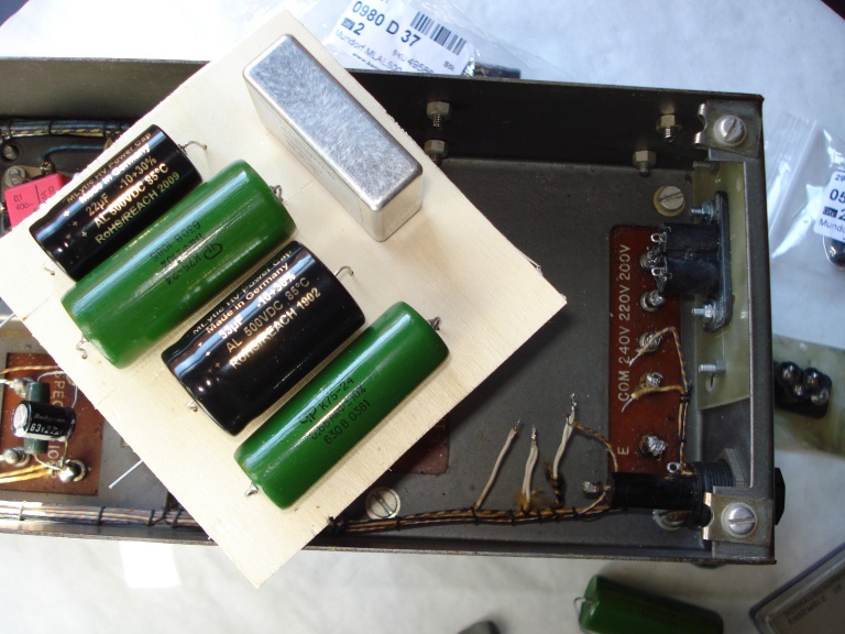
of the components both for electronic "tricks" present. Those are the 2 large photos, before and after restoration
| |
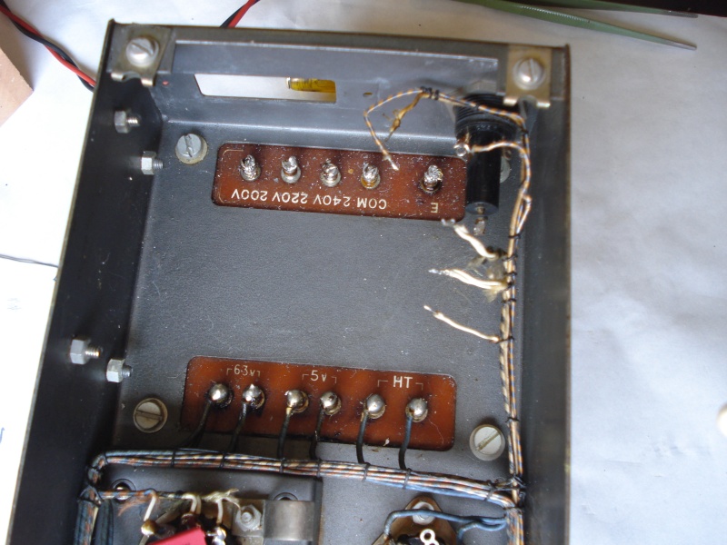
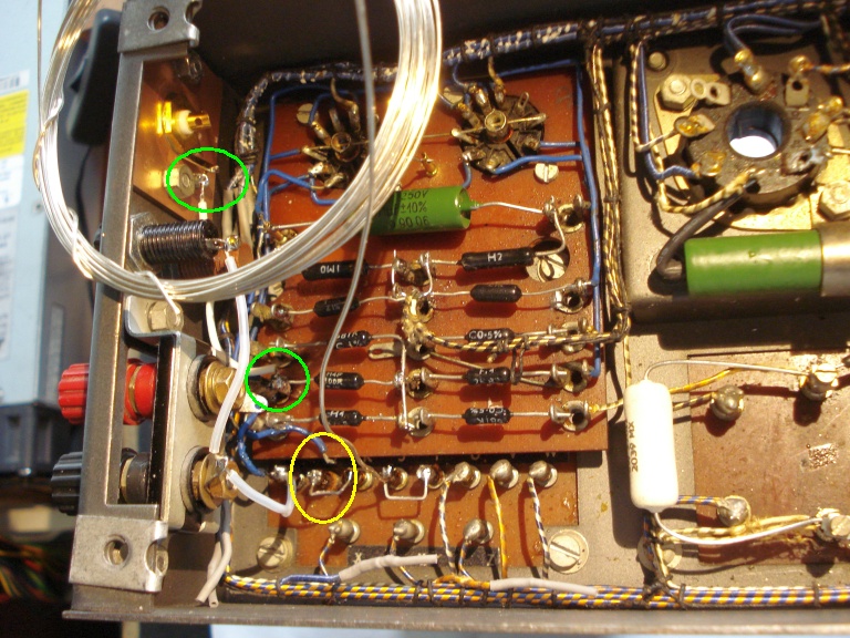
| Fig.1, on the Internet you can find thousands of quad II photos, but the best part is the interior for the arrangement of the components both for electronic "tricks" present. Those are the 2 large photos, before and after restoration |
All trademarks mentioned and links are presented here for informational purposes only and to confirm statements made by the author. The author of these pages DOES NOT receive any remuneration from the mentioned brands and the listed links.
In any case if you decide to use the suggestions on this page you do so at your own risk. Repairing electronic equipments, even just opening it, can put your life at risk, so don't do it.
If you do not accept and/or not understand the statements in this disclaimer, written in blue, exit from this page immediately.
Everything exposed in this web page is only a suggestion, probably you won't obtain the aim from you prefixed following it.
Be carefull, a true collector is looking for a) original items without any replaced parts, and with all accessories b) or if a Critical Restoration has been done that it is possible to go back to the original version.
A dear friend of mine, who had been known for 30 years, after years and dozens of attempts managed to buy a pair of Quad II (or Quad 2).
About 91,000 were produced and the last series had some retouching in the design (they say improvement) but if they find few, some massacres, others degenerate, others in Mint-Condition but with crazy prices.
This couple had the original frame, some component replacement and a set of exceptional valves. The price? Honest, stands average.
Also I am a chemist with the hobby of HiFi, tube amp, and restoration from my early life. With the hobby of restoration I have the opportunity of "ear" some equipments impossible to buy for me.
Possibly the most famous amplifier in the history of hi-fi.
Even for the history of the S.P Fidelity Sound Systems (then The Acoustical Manufacturing Company Limited and finally Quad Electroacoustics Limited) There are hundreds of pages in Internet. Why write another one?
After days and days of research here are links to the history of this brand and on the products, unfortunately tomorrow these pages could disappear (you wanted ephemeral internet, you keep it).
Part of history are definitely the original brochures and illustrative booklets, we thank UK Hi-Fi History Society for having collected them and photographed.
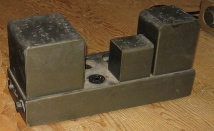
Some Quad II was produced for "special applications" for professional, industrial, scientific use, see at the end of this thread, more see those photo: with larger power trasformer, for professional use.
All the technicians you know will tell you that they know how to repair a quad II. But the risk of disrupt completely a collectible device is really high, look fig.1 and all the errors made by that repairman.
Fortunely there is "a wizard" of the vintage Quad (not only!) still today working, Sir Keith Snook, on the web pages of him can find news, schemes, photos of repairs made in many years of careful work.
Also Mr. Snook is a lovable person who dispenses tips and suggestions and from which you can buy some unobtainable parts at "human" prices.
 |
| Fig.2, the main web page, the link to Quad page is this one |
For completeness must be quoted some other famous quad repairers, following are someone:
Repair and restoration are not synonymous. Italy has the largest number of cultural sites recognized by the UNSECO, its history, from Neolithic, to the Romans to the Renaissance makes fit a reference in the field of Cultural Heritage, not marvel that techniques, methodologies, procedures and ideas about restoration have been developed, with even a careful terminology to describe the "types" of restoration.
It is difficult to explain the difference to non-experts, in universities, Prof. Giorgio Bonsanti is often mentioned for his "Paradox of Brustolon", "if a chair breaks, he is repaired. If the chair is from the Brustolon, it is restored" (Andrea Brustolon, was an Italian sculptor in wood in 1700. He is known for his furnishings in the Baroque style and devotional sculptures)
Among the many art historians that dedicated to the definitions we could mention Marco Dezzi Bardeschi "Restauro è ogni intervento che si proponga l'obbiettivo della permanenza nel tempo, per quanto relativa, della consistenza fisica del Bene materiale ricevuto in eredità dalla storia, del quale si possa garantire la conservazione di ogni sua dotazione e componente in uso attivo (meglio quest'ultimo se originario o almeno comunque ad alta compatibilità e minimo consumo), da perseguire opportuni e calcolati nuovi apporti di progetto (funzionali, impiantistico-tecnologici, d'arredo), in vista della sua integrale trasmissione in efficienza al futuro".
Some definitions:
Of the 200 descriptions of quad II interventions that are on the Internet almost all define "restoration" but how many of these welder operators have studied only one of the previous definitions?
The application of the concepts of the restoration to objects of real life, even more to collectible objects, is a complex problem, we make 2 examples: a) making participate a Lancia Aurelia B24S Spider America, from 1955, carrozzeria Pinin Farina, to a Concours d'Élégance requires a scientific restoration, b) bringing to navigate, but safely, a Gozzo Sorrentino, all wood, of the 50s, build by dockyard Aprea requires a philological and conservative restoration.
First we need to recognize the Quad II the status of historical, artistic, collectible object, as an Alfa Romeo car, or a Caltagirone lifter centerpiece ceramic, all produced in 1954.
Recognized Quad II as a historical object the consequent restoration must follow 3 postulates:
In your dictionary probably there is not the word "destroration". It is contraction of two word Destruction and Restoration, invented by history teacher Dr. Benni Leemhuis describing an intervention on a Egypt Pyramid.
Some example of Destroration are often cited by art historians, an example can be obtained reading this page.
What about Quad II? A true collector is looking for a) original items without any replaced parts, b) or if a Critical Restoration has been done that it is possible to go back to the original version.
Lacking the previous 2 statements the object (not only for me) has a value of zero euros.
 |
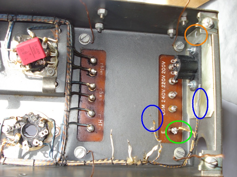
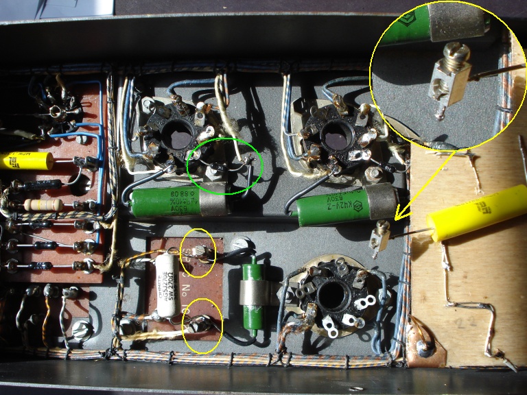
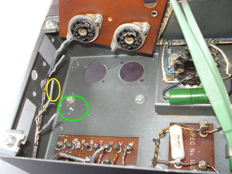
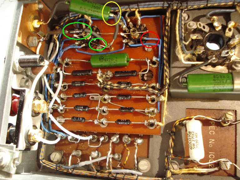
| Fig.3, for me a Zero euro value destroyed Quad II, see the green circles, but having in the hands probably we can find more and more, starting with painting. Large photo is here |
However, there are cases in which a critical restoration (or even more a scientific restoration) is very difficult and for which the cost exceeds a lot of commercial value, below 2 cases we hope have resolved with a success.
 |
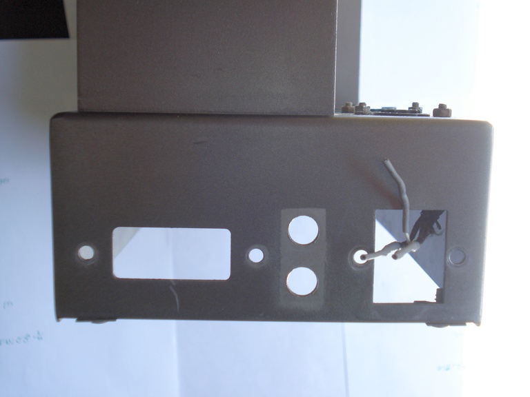
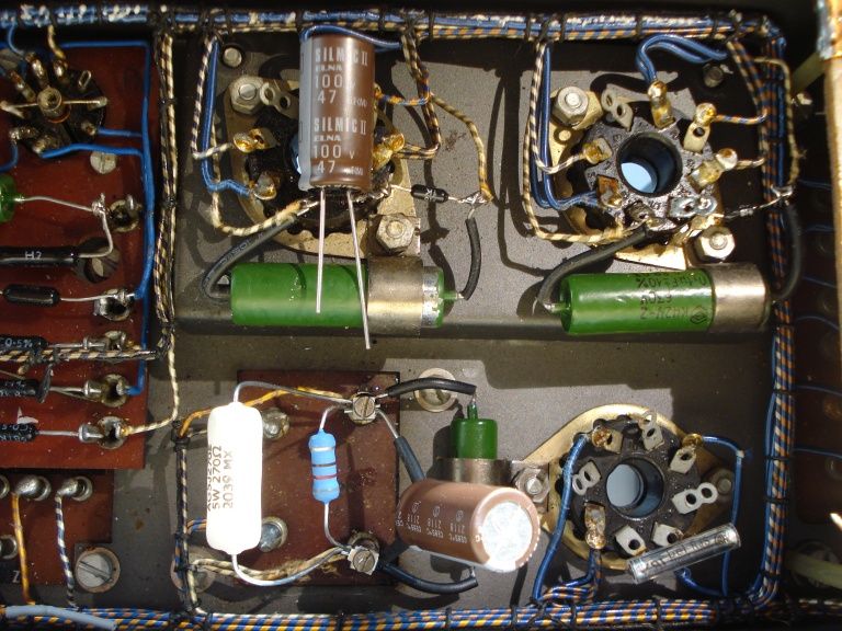
| Fig.4, unfortunately a Quad II in poor cosmetic condition, probably working or not. In the second photo a dismantle to solve problem like this |
Let's say it better: Needless to say, you must avoid 'modififed' QIIs like the plague. A handful of companies in the past have persuaded people to fit voltage doubler power supplies, EL34 output pentodes, anything they can do to boost the power otuput. I'm afraid it's all a load of cobblers. Watch these vandals, Mr. Walker know best. QUAD IIs were designed for 15 watts output - not fifty. from H. Boardman's.
It is not the fault of P. Walker but of those who used it without any respect but there are some Quad IIs with the transformers either burned or "cooked".
If the winding is really interrupted, a DMM is enough to know but a "cooking" transformer is difficult to diagnose, especially if there is a loss of insulation, perhaps in hot conditions or under a difficult load.
There is little to do in these cases, luckily there are some Quad transformer winders (maybe 3 or 4 in the world) and also with an adequate cost.
Actually the Quad II does not have design or construction defects. Wanting to insist we can find three in the schematics and one in the layout, let's see them.
Peter Walker's scheme follows exactly, rightly, the Philips or Mullard datasheets. But today some further study on the rectifier valves has been done so let's talk about the first "defect".
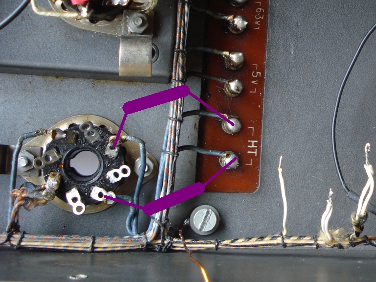
First lack (insoluble), in the photos of fig.5 you can see the original Philips diagram on the left, and on the right the Quad II scheamtics, below the schematics from Emisson Labs website (one of the 3 best valve manufacturers). If unfortunately the power transformer burns out (not by itself but for some other internal damage) you could ask the rewinder to do a center tap for 5V.
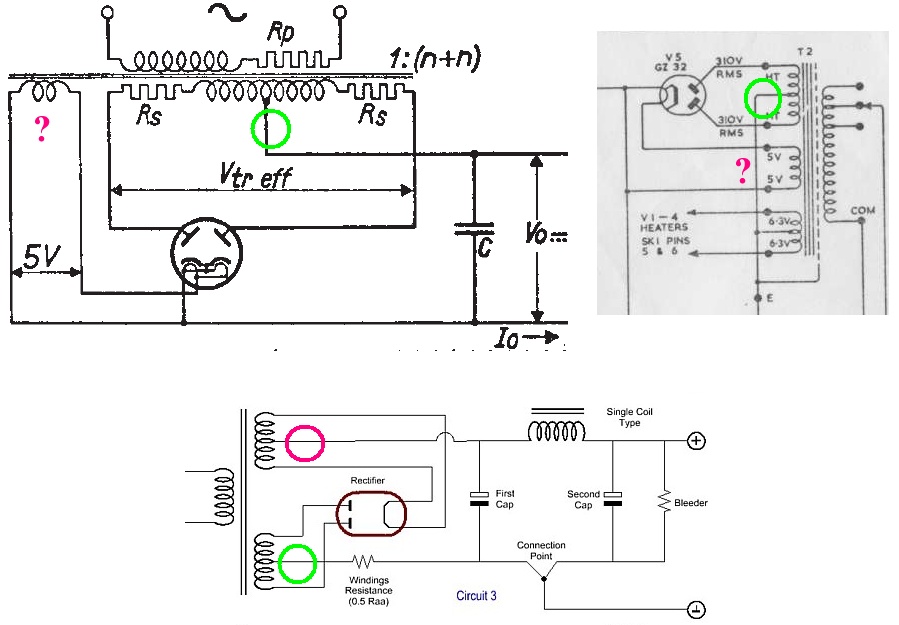 |
| Fig.5, see the green circle on the 3 schematics, all OK. But the purple circle suggest to obtain the positive path from the center pad of 5V filaments. Better with this we have a small resistor Rs before the capacitor and e few mH as filter. |
Second lack (difficult to solve), all laboratory instruments, electro-medical devices, measuring instruments, even your PC, if they use a choke they use a common-mode type. HiFi and all the Audio cost too much to mount a dual choke! In any case the audiophiles pay the 10,000 euros having or not, poor f.....
Let's look carefully at the diagram with the common mode, if Rt (sum of the various Rs of the transformer) reaches 100 ohm we could mount a 33 µF as the first cap, the dual chocke isolates the second capacitor that can even rise to 100 or more µF (depends on the Rseries) and moreover both the positive and the negative are filtered by a choke. Too good and too functional to mount on ANY modern HiFi. Maybe you could find a place in the case of the Quad II so even the anode voltage would have its choke, indeed no 2, but is this a restoration?
 |
| Fig.6, one choke is present, in green. the other not in purple. I dont like the Bleeder resistor (yes I know necessary by law) but this resistore draw to 0 (zero) all capacitor every time switch off halving the expected life. |
Third lack (easy to solve), the 230V power socket is in front near the output terminals and the RCA pin, an unfortunate position. But the fuse, the voltage changer and the transformer are on the opposite side. The 230V travels on thin sausage knot wires with the high voltage with the output signal, etc.
 |
| Fig.7, immaculate Quad II, how nice it would be to leave it like this, but after 60 years? In purple the path of the 230V inside the sausage-tied wire |
Fourth lack (easy to solve), Everyone, indeed almost all, the preamps and the vintage valve amplifiers not mounted the Grid-Stopper. I don't think the famous and praised tube designers, like Mr. Walker, did not know the problem but avoiding them save money and time in the construction
As already mentioned above, today with the crazy growth of wireless connections and all radiofrequences the possibility of mounting a filter, made by a single resistance, sinks a miracle. And we use it.
The true experienced audiophile sentencia: Grid-Stopper. never there passes the signal. The problem of some mind-disturbed audiophile is "the signal", but the crazy does not know that practically in every resistance of a valve amplifier pass the so-called signal (as exmaple in the R of PI Greek C-R-C filter in supply, if present!). To the country fool, many years ago, everyone knew that you had to always tell him to yes, yes.
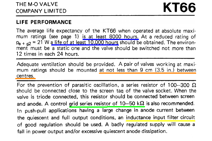
We are looking for some examples of use, the first on the DataSheet of the GEC producer of KT66 used in all Quad originally. The second example in an Audio Note UK amplifier, which uses an ECF80 for input gain.
 |
| Fig.8, in green the Grid-Stop suggested, in yellow as alredy said the choke suggested |
Other two statements of fig.8 should be highlighted: the first one is the minimum distance between tubes that practically NO manufacturer respects; the other one is the expected lifetime that contradicts the usual audiophile, expert in nothing, who killed the NOS market changing tubes like paper tissues. A stupid person.
Still on the grid-stopper, we finally see it used on some Audio Note UK schematics, like the one in fig.9 taken from the 1995 P4m amplifier. The use of the grid-stopper on each tube is also seen in the AN-UK Ankoru amplifier (see a review) and in the amplifier of Audio Note Kit EL84 push-pull a famous Kit.
 |
| Fig.9, output stage of P4m, 300B mono amplifier from AN-UK, here the complete schematics |
Historical research, finding the documentation, studying the schematics, analysing the work done (well or badly) by others, do a critical analysis, studying the original components, are necessary steps preparatory to any restoration, but they cost a lot of time. For this section, we can estimate at least 15 man-hours of work.
The third lack is easy to solve. Indeed having to get our hands on, we add an EMI filter. Today a lot of trash passes on the electricity network (remote reading of meters, powerline ethernet, PLC, e.g.). Do you have to insist? Every laboratory equipment has a VDE socket with an EMI filter connected, but the HiFi a preamp of 20,000 euros costs too much to be able to afford it.
Move the mouse over Fig.10 to see the power supply side as arrive and after claenup. be careful to remove old solder on the turrets.
 |
| Fig.10, cleaning the power supply side of this Quad, also removed the dangerous voltage changer |
Having decided to move all the power supply to the back of the frame, we need to find a panel socket that allows us NOT to drill the frame itself. The classic C8 socket would be fine but the EMI filter needs ground to work.
The simplest choice would be an IEC-320 C-14 tray perhaps already with built-in EMI filter. But it's up to saw the frame (goodbye reversibility).
A solution that allows NOT to cut the frame is the C6 socket used in notebooks. However they don't come with the built-in filter, so you have to add a box with EMI filter inside the case.
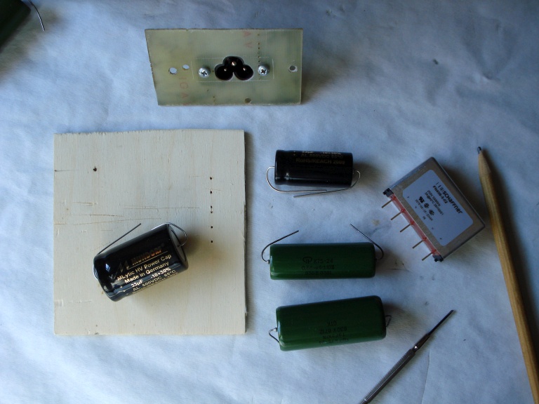 |
| Fig.11, the components to be fixed inside the case to upgrade the power supply, see the handmade frame to mount the C6 socket with engraved the dimension of original rectangular hole |
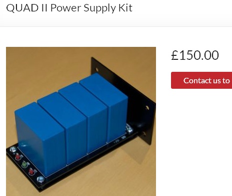
If you only want to replace the two capacitors C4 and C6, you can buy a ready-made pair on a board, but beware of the cost 150 pounds, here is a seller. All components in fig.11 cost well under 150 GBP!
Let's start by building a board by hand to fix the C6 socket, then we carefully unsolder the original (solid core) wires and isolate them with heat-shrinkable. In Fig. 12 part of the work in progress.
 |
| Fig.12, the holes in handmade C6 board fix the original holes, in orange? Resold the ground of transformer, in green. Reversibility, the original solid core wires, in blue, was cleaned not cutted and insulated with heat-shrinkable |
How to fix the components of fig.11 in an empty space, in a reversible way? Do we reinvent the wheel or are we inspired by some audio myth? No PCBs, no perforated bases, just wiring in the air using the component leads (as far as you can).
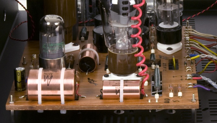 |
| Fig.13, Audio Note UK, the M10 use marine plywood and component leads, very functional and really nice to look at (look at the non-magnetic stainless steel bolts, the ceramic lifter beads, the cables terminations of which a free pair) |
To do some tests with the dimensions of the components, below the list, and with the spaces available we cut a cheap plywood board and make some holes for the leads, go there?
Components to be fitted:
 |
| Fig.14, let's do some tests with a wood cutout, draw the paths in pencil, let's study how to fix this board |
Obtained the measurements of the base and the holes to pass the leads, we can buy the phenolic marine plywood pine, cut the wood, reinforce the corners with a folded copper sheet and mount the components of previuos list.
First we must prepare the area that will accommodate the base: with fixing turrets, with the passage of all the necessary wires, with the fixing of the C6 socket.
 |
| Fig.15, starting from fig. 10 we solder all the wires, isolating them, we reassemble the fuse and socket, we measure one last time "the spaces". The black wires arrive to n.2 (see list above), the blu, orange and red start from n.2. The 3 short white wires was original |
For the assembly we try to take inspiration from fig.13 (if ever possible) using the leads and reinforcing with the wire where the more current is needed.
 |
| Fig.16, move the mouse to see the two sides of this board. See the case of the Schaffner EMI filter insulated by 2 layers of LD-PE, not show but the capacitors are fixed to the board with a line of glue |
The HT fuse: searching the internet you will find various suggestions on adding a high voltage fuse. The thin wire of the HT winding of the transformer must be protected!
The fuse cannot be added before the choke (it would not protect against a short circuit on C6), it cannot be installed at the output of the GZ32 (it does not protect against a short circuit inside the valve).
The only solution is to mount two of them on pins 4 and 6 of the gz32 octal as a bridge. Reversibility: easier than expected, see fig. 17. But the value?
If you decide to use them, it is better to use through-the-hole fuse, no holder or clamps or sockets or clips (but if they burn a careful work with the desoldering unit is needed to replace it without damaging the turrets and the socket).
I must ask the owner IF mount or not the fuses.
 |
| Fig.17, the purple color draws the position and connections of 2 fuses (after unsoldering and insulating the 2 sides of blue wires). Remember to cover them with a Teflon tube. |
Once the restoration of the power supply section has been completed, it would be necessary to calculate the man-hours spent on this part of the job, taking into account that you start by searching for the best components in at least 5 online catalogues, filling the various shopping cart, paying, collecting the package perhaps at a delivery point, then you start to study how to assemble the components, cutting and soldering and finally wiring. Calculating everything, I think we can count 30 hours of work for this section.
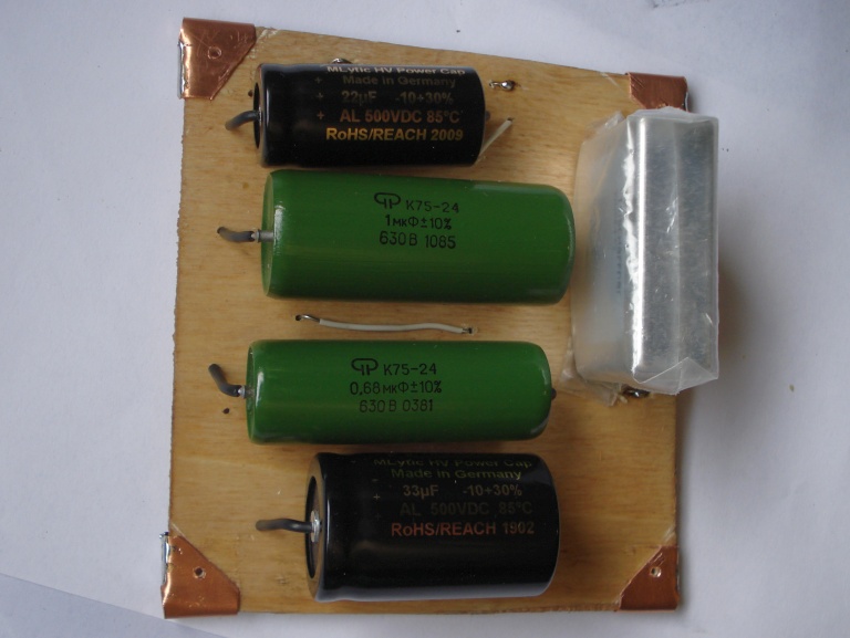
The owner, rightly, prefers paper and oil capacitors as AC coupling of the final tubes. I don't like patchwork so together we decided to use only 2 brands and models of capacitors, Mundorf MLytic HV Power Cap and a Papier in Oil capacitor (plus an Elna Silmic II for C5).
In agreement with Keith Snook and with the owner were chosen the Russian PIO capacitors, the green model, military, with the right voltages.
Components to be fitted:
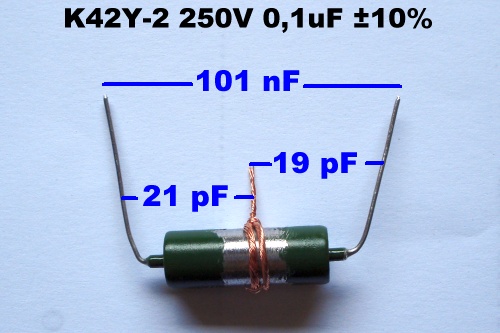 |
| Fig.18, measured values for K42Y-2 capacitor. The four 630V K42Y-2, 0.10 µF show the same values to case from 19 pF up to 22 pF. |
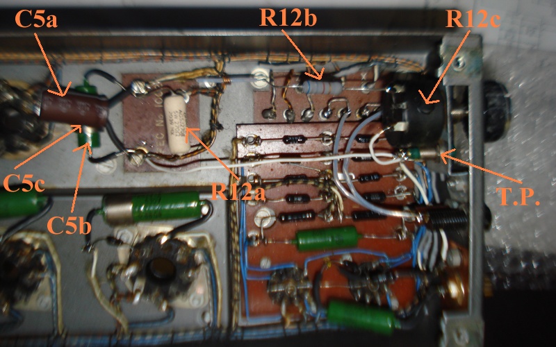
The green paint must be removed to ground the capacitor case itself. With the clamps, used who knows why by Mr. Walker, fitted you get 3 capacitors. With a fine file, copper wire, and an RLC meter we can get Fig.18. Please refer to the Keith web site for the appropriate, right, explanations.
The power tubes use cathode-bias polarization. One of the 2 or 3 methods used in almost all tube amplifiers but here only one resistor is used for the 2 cathodes of the push-pull so the working current cannot be measured (often called common cathode bias). For the way the Quad II is built, excellently, there is no way to change the value of the current, goodbye bias.
With modern KT66 tubes, some very good, some good, (maybe exceptional like those that will be produced in a couple of years) that do not respect the GEC specifications, not having a bias setting is a big problem.
 |
| Fig.19, see the terminal block with screw in yellow. With this mechanical trick you can change the working current of the 2 KT66 by varying the value of R12 resistance. In green the grid-stooper |
Using a fixed resistor of 270 ohm 5W and putting in parallel to it a resistor of 560 up to 1500 ohm you can get many values for R12 anche change the bias current. The 270 ohm resistor should be soldered as if it is the only R12 resistor, so that a false contact in the parallel will not damage the power amplifiers.
| Tab.1, calculation of Rtot, W and current (stated 26V on cathode) changing R parallel | ||||
| R (Ώ) | Radd (Ώ) | Rtot (Ώ) | W Radd (W) | I tot (mA) |
|---|---|---|---|---|
| 270 | 1500 | 228.8 | 0.45 | 113 |
| 270 | 1200 | 220.4 | 0.56 | 118 |
| 270 | 1000 | 212.6 | 0.68 | 122 |
| 270 | 820 | 203.1 | 0.82 | 128 |
| 270 | 750 | 198.5 | 0.90 | 131 |
| 270 | 560 | 182.2 | 1.21 | 143 |
Solved the problem of bias-setting when KT66 was changed the problem that remains is the measurement of the current of the single valve. Also with terminal block we can easy change the chatode capacitor for value and for brand.
To measure the cathode current in cases of common bias resistor like this you can modify the circuit to build a hybrid common cathode bias in which the individual cathodes are connected to a small value resistor before converging on the true bias resistor.
Another method is to use a female-to-male octal adapter to measure the bios. Just disassemble the valve, from power off, insert the adapter under the valve to be measured, power on, wait several minutes and measure as prescribed by the user manual.
But the Quad II schematics is so simply-complex that adding any R on the cathode, either hybrid or through an adapter is not a good idea.
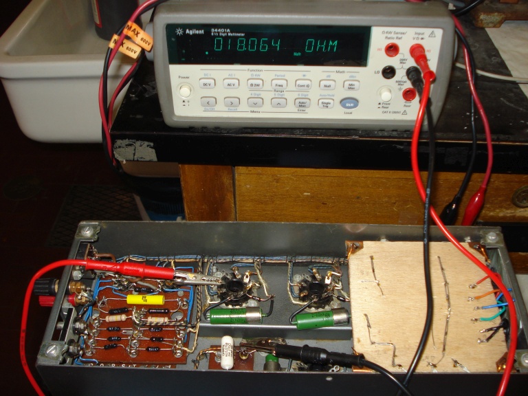 |
| Fig.20, using a high quality ohmmeter, with its null function, the resistance between pin 8 of the KT66 and resistance R12, including wires and windings, can be measured. Write down these values and then use them to calculate the current. Move the mouse over to see 2nd photo |
I am not suggesting changing the cathode circuit as in H. Boardman's article, as the single R12 allows you to balance an imbalance between the power tubes with famous Common Cathode Resistor circuit.
But mismatched tubes in any case produced mismatched current, dissipation and harmonic distortion. In fig.20 an easy solution, carefully measure the DC resistive value of the two cathode filaments of the transformer and then use these values to calculate the current.
Necessary or not, if you like, the measure of the single tube current is solved.
Completed the KT66 section we can calculate the man-hours spent on it. An optimistic calculation would be 10 hours.
Let's now pass to the input stage and phase shifter that uses the EF86. As usual we refer to Keith or other websites already mentioned for the study of operation, let's see the restoration instead.
There are immediately 3 things to say :
Let's see first the photo of how the power amplifier was repaired, as usual in the caption some considerations on the photo itself.
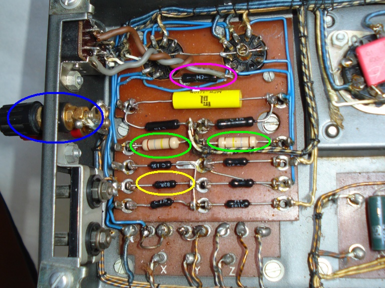 |
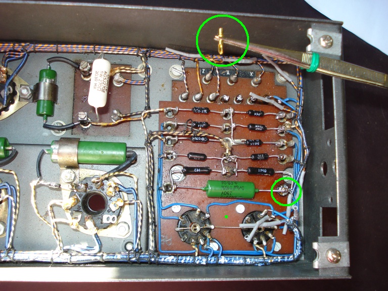
| Fig.21, why 2 resistors have not been changed (in green) when others are excellent Holco? In blue 2 non-original binding post, in yellow a resistor that seems of different value from the schematics. In purple a strange resistor (input and bias of V1) of 2W |
In the next figure removed all the sockets you can see better the board. For reversibility all the wires have been desoldered and insulated with a heat shrink, then they will be tied to the others.
We can see some problems that are described in the caption and highlighted with colored circles, something is unrecoverable given point a) above.
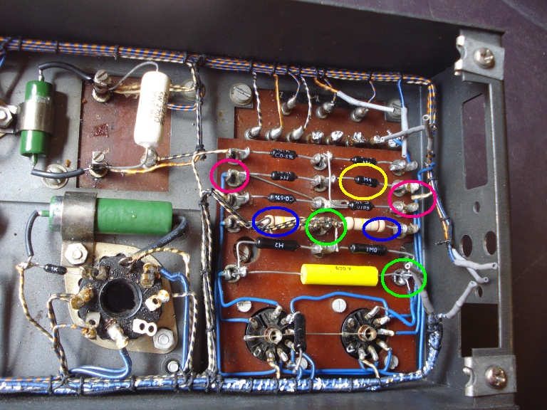 |
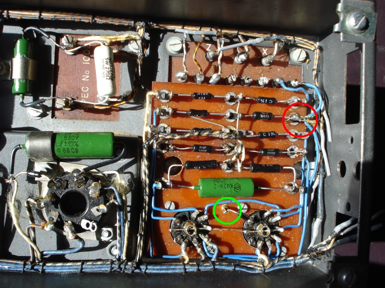
| Fig.22, the other amplifier, measured the resistor highlighted in yellow is really wrong, in blue the 2 resistors to be changed, in green the broken turrets, in purple 2 wires that came off just moved with a tweezer |
Do a cleaning with a good desoldering station before mount the new components.
Components to be fitted:
 |
| Fig.23, the board with resistor and EF86 sockets must be lift to find soldering drop, in green, and other dirty. The tube sockets must be cleaned, in yellow the original cables cleaned and insulated |
Sockets are a separate issue, if you want to replace them you need two McMurdo British made B9A like the ones in fig.23 and three McMurdo Octal sockets.
The Quad has always mounted practically only this brand of sockets, so no Teflon, Ceramic, etc..
 |
| Fig.24, unfortunately a hole between the 2 sockets is needed to mount a turret, the green point, to support the grid-stoper and the input capacitor |
The board of resistors is almost finished, an original turret completely broken that holds the capacitor has been replaced with the one in the green circle (fig.24), another is also used for the grid-stopper.
In the following picture the board with the EF86 is finished, all with the excellent Holco resistors.
 |
| Fig.25, finally the entry and splitter board is finished, we have highlighted 2 points. With a green circle the new grid-stopper and with a red circle the ground |
The red circle in Fig. 25 should be better described, it is basically the centre-star of the negative of both the power supply and the input circuit. Hence great attention to the soldering at this point and we could converge the RCA jack case there.
The input and phase shifter stage section is also finished. The calculation of man-hours in this case depends very much on how the board was reduced/damaged and the work required, here we could estimate 15 man-hours of work.
Let us now move on to the inputs and outputs side. We have freed this side from the cumbersome (dangerous) presence of the 230V and can now dedicate ourselves to improving this section as much as we can (with reversibility).
As expected, we start with a good cleanup.
 |
| Fig.26, after disassembling all components on the input side, the original holes are visible and the old wires are covered with heat shrink tubing. The frame is not repainted, only the paint that is exposed to light changes colour after 50 years! |
Components to be fitted:
On this side, only the input RCA pin and the output banana jacks have to be placed, since the 230V has been moved to the back. For the RCA pin-jack we have seen many solutions, the most beautiful is to use the rectangular hole for a baseplate and mount on it a good RCA.
 |
| Fig.27, £185 for two replacement parts, certainly good, but without component branding, neither pin-jack nor capacitors! Move the mouse to see other photo. This is the original link |
The magnificent Switchcraft RCA pin, our selection, should be fixed on a double copper-clad FR-4 laminate board after proper drilling, without isolating it (or you can use a no-copper FR-4 board without copper to isolate it). In place of 150 pounds we already use Mundorf MLytic HV and Papier in Oil!
A 2-conductor cable is usually used to connect the speakers! But having space on the chassis and wanting to do something different from the usual, but also functional, and without making more holes or cuts (the reversibility), we can try a true biwiring.
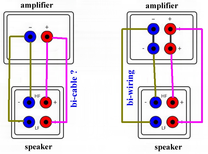 |
| Fig.28, on the left what many consider bi-wiring but in fact is a bi-cable (contact problems on common points on the amplifier), on the right the real bi-wiring already provided by the amplifier itself |
On the necessity or not of bi-wiring (the real one, on the right) discussions will never end, but having space we build an almost unique Quad II. You want to see an example of an audiophile who has not understood what bi-wiring is for (if any), halfway down in this link, read the comments at the bottom!
 |
| Fig.29, let's see the inlet/outlet side. Unfortunately the original square bushings are hard to find (also used by the Quad 33) here replaced with a vintage pair. The copper of the PCB that holds the RCA pins is covered with a layer of wax, on both sides, to prevent oxidation |
Decided for bi-wiring you need to connect these bushings to the output transformer in the best possible way. The distance is little and allows us to dare a little more than the project of P. Walker.
Strangely, the original wiring has a multicore wire for the ground (P of the transformer) and a solid core wire for the positive (T of the transformer). But the positive is the one that over the years will undergo constant switch and soldering between 7 et 15 ohms!
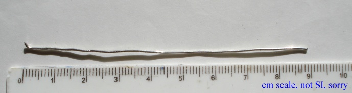 |
| Fig.30, with only 90mm of silver wire we can connect the output stage at best (2 pieces) |
Yes, for 2 pieces of 90mm wire we use silver wire with 99.99% purity and 1mm2 diameter. Many amplifiers, both old and modern, are lost at this point, the output connection. You can find an analysis on another of my pages.
High purity silver wire (almost 99.9%) is not overly expensive if you know where to buy it. It is used in satellites (light and with minimum resistance), in the electronic industry (the real one) and in chemistry and physics laboratories. Remember that none of the brands mentioned sponsor this site, but to understand what might be its cost here are some links:
 |
| Fig.31, the Ag wire for the negative is already soldered to P, the positive to Q still needs to be cut. In yellow a problem with the solid core cables, solder the bridge between Q and R, the blue cable has pulled back like a spring. In green the RCA ground to the center-star |
Solved the problem of connection between transformer and output jacks still missing the path of input signal that must be brought up to the grid of EF86.
If the Quad II is connected to its preamplifier or to a well-built modern tube preamp, it will not suffer from the presence of a DC input voltage.
On the other hand, various transistor/fet preamps suffer from the problem of DC leakage. We can't say the brands but with 2 friends who graduated in electronics we measured hundreds of mV of leakage from a very expensive, modern, tube preamp. The purists/presumptuous/gurus/shamans of chatty (not studied) high fidelity will scream at the scandal, but a nice Paper in Oil at the input has to be added, today, necessarily.
By the way, the Quad 22 has a 0.1 µF output capacitor (for C16, and you couldn't expect less from Walker's genius) but after there are filter circuits, bass, treeble, slope and so on.
 |
| Fig.32, in the picture, yellow circle, the input PIO connected to the turret already seen, the 2 green circles show the R grid-to-ground and the grid-stopper, the red circle shows the original connection of the 2nd EF86 |
On the grid-stopper on the first valve, let's not go back over it. On the other hand, on the original 1.5Mohm there is some discussion. It was used to not load at all the preamplifier that comes out of anode of 12AX7 and mounts aabout 100Kohm as R output to ground (R41=27K0 + R42=68K0).
Actually the preamp, seen from the power amp, shows a much more complex circuitry, with R-L-C filters after the amplification stage that also use the power amp in their equations.
In addition, reading many datasheets of the EF86 we can read values of Rg1 from 0.15 Mohm up to 0.68 Mohm with a design with even 3 Mohm.
Modern transistor amps, RCA unbalanced input, usually have a 47Kohm as R-load, valve amps have 100Kohm. Sorry we can't follow Walker's circuit but let's take down the Rg1 to 1 Mohm.
In the red circle of fig. 32 you can see that for V2 we have not added the grid-stopper, the circuit is too complex as phase shifter and driver and also as feedback arrival point, better not to touch it.
The output side section if finished. To calculate the time spent we must account the cut of RCA board, the modify of binding post, cabling and so on, we could estimate 10 man-hours of work.
Finally we have to decide the value of R12. Thinking about all the new KT66's that maybe don't respect well the datasheet of Philips or General Electric Co (Osram subsidiary) we choose 203 ohm from Tab.1.
Not connected (n.c) or not present (n.p.)? To fix on the socket the fuse chosen for the HT of the GZ3x which pin do we use? Better n.p., i.e. that doesn't exist on the valve at all, instead n.c. indicates a pin that is on the valve but internally is not connected. But bringing inside the valve almost 400 Vac doesn't seem a good idea.
 |
| Fig.33, bottom right the HT fuse that bridges pin 6, anode and pin 7 transformer wire. On the screw turrets are fixed C5 and R12, pay attention to the screws. |
Note the assembly of R12-C5 on one side the 2 capacitors, on the other the resistors that heat up. Be careful to tighten the screws! After inserting the two leads into the holes you have to "lay down" the screws. Then use a large long nose pliers to hold the turret firmly in place and use the screwdriver to tighten the screw, but not too tight. Otherwise you will certainly break the weld and perhaps the turret.
The restoration (philological and conservative) is over, and now what?
Calculating the hours spent in this section seems simple, but think about how much testing goes into finding the right R12 that produces a cathode current of about 130mA. Fix the resistor, 10 minutes of heating, measure, fix a new R, etc. Same on the other amplifier. For this section alone we can assume at least 25 man-hours of work.
The original scheme provides the use of the GZ32 as a rectifier valve, but it is often recommended to replace it with the more modern GZ34, why?
Because the GZ 34 consumes less current for the filament, it can produce higher output voltages and also higher currents (but it depends on the polarisation).
With Mundorf HV and PIO 630V capacitors, a few more volts of anode are of no concern, but for a transformer with many years of honest work, lower current consumption is a good thing.
But will this lower filament current consumption be true? Let's measure various valves, both vintage and modern, and compare the results.
| Tab.2, measurement of the filament current of the 3 valves of the Quad II | ||||
| tube type | V supply (V) | current (A) | power (W) | note |
|---|---|---|---|---|
| GZ 32, Miniwatt Dario, vintage fat boy, black socket |
5.0 | 2.39 | 11.95 | more then 6A at start |
| GZ 32, Miniwatt Dario, vintage fat boy, black socket |
5.0 | 2.29 | 11.45 | more then 6A at start |
| GZ 34, Genalex, Gold Lion, new cylindrical, russian |
5.0 | 1.92 | 9.60 | soft start? |
| GZ 34, Genalex, Gold Lion, new cylindrical, russian |
5.0 | 1.91 | 9.55 | soft start? |
| GZ 34, Mullard, vintage cylindrical, black socket, made G.B. |
5.0 | 1.86 | 9.30 | . |
| KT66, Valve Art, new fat boy, black text, china |
6.3 | 1.40 | 8.82 | . |
| KT66, Valve Art, new fat boy, black text, china |
6.3 | 1.39 | 8.76 | . |
| KT66, Valve Art, new fat boy, black text, china |
6.3 | 1.41 | 8.88 | . |
| KT66, Valve Art, new fat boy, black text, china |
6.3 | 1.40 | 8.82 | . |
| KT66, TAD, new fat boy, brown socket |
6.3 | 1.35 | 8.51 | . |
| KT66, TAD, new fat boy, brown socket |
6.3 | 1.36 | 8.57 | . |
| KT77, Gold Lion M.O. vintage cylindrical, brown socket, made U.K. |
6.3 | 1.31 | 8.25 | true Gold Lion |
| KT77, J.J. new cylindrical, black socket |
6.3 | 1.44 | 9.07 | red label |
| KT77, Gold Lion new cylindrical, black socket |
6.3 | 1.56 | 9.83 | Russian |
| 5881, CBS, vintage cylindrical, brown socket, made USA |
6.3 | 0.89 | 5.61 | . |
| 5881, CBS, vintage cylindrical, brown socket, made USA |
6.3 | 0.88 | 5.54 | . |
| EF 86, Mullard, vintage cylindrical, small shield, made G.B. |
6.3 | 0.19 | 1.19 | . |
| EF 86, Mullard, vintage cylindrical, large shield, made G.B. |
6.3 | 0.18 | 1.13 | . |
In the worst case 32.11 Watt of power transformer was waste only to "light" the tubes.
I'm going to ask various friends to lend me some KT66 GEC, vintage GZ3x, vintage KT77 and similar one to complete tab.2 with filament measurements. Already we can see that the GZ34 really have a lower consumption and that you could make an attempt (it seems never tried before) to replace the KT66 with KT77.
Reading the tab.2 the new Gold Lion KT77 (??) tubes unfortunately load more current of original vintage for filament, but if you find the old, vintage, M.O. Gold Lion surely fit better of KT66 and save a few watt from transformer.
But we are running the power amp. only, no 22 Preamp. Inside the Quadd 22 there are 4 small tubes, 2x EF86 (200mA) , 2x ECC83 (300mA) with filament at 6.3V and probably consuming 2x 0.2A + 2x 0.3A = 1.0A so the power transformer can supply about 6W more on 6.3V. We can fit the al KTxx is we do not use the 22 preamp, not KT88.
Anode to Anode impedance? The original M.O. KT66 datasheet suggest 5000ohm in the fixed bias configuration, the original M.O. KT77 datasheet suggest 6000ohm but for a higher voltage, so we can swap the two tubes with a little mismatch.
Powering up after a restoration where all the capacitors, resistors and other parts have been replaced is a delicate moment. Even an oversight in the assembly could "only" fail to operate the equipment (and we start again with the troubleshooting algorithms) or do worse damage than we started the restoration for.
But sooner or later this device will have to be turned on! Let's look at step by step path to limit the risks.
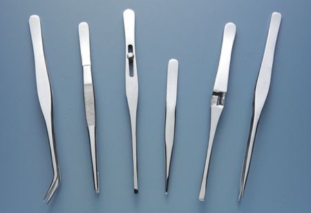 |
| Fig.34, an example of tweezers used to pull wires to check soldering (photo from a famous American chain store) |
Each design system has its own method of testing before ignition, lokking the Quad II we see a mixed system between point-to-point wiring and on-turrets fixing.
Given also the 50 years of age and the use of some solid-core wires a good method is to use tweezers to gently pull and push each wire at the point near the solder.
Using this method, 2 broken wires were found but resting on the solder (one for each end) that would have driven anyone crazy during troubleshooting.
Almost all HiFi equipment contemporary with the Quads had both a user manual and a service manual dedicated to service centers. The tube Quads did not, perhaps they were very reliable, but perhaps so simple that the manufacturer did not think a service was necessary.
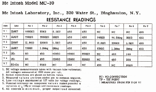 |
| Fig.35, the table of measurable resistances, at power off, copied from a book of Howard W. Sams & Co., Inc. dedicated to the famous McIntosh MC30 |
But in the manuals of that time there was much more, please read page 4 et 5 of what is called MC30 Instruction Manual, always from McIntosh!
A table of resistances like the one in Fig.35 is very important both if you are starting to evaluate the functional status of an amplifier as in Fig.1 and/or if you are going to turn it on at the end of a long restoration.
To obtain the table below those components to be fitted:
To obtain correct values the amp must have been turned off the day before and all tubes must be removed. After the power on we will try to comment almost every line of Tab.3.
| Tab.3, Resistance to ground (no tubes) and DC voltage measured with HP-Agilent 34401A, AC voltage was measured with 1000Hz, 1W on 8ohm load |
||||||||
| s.n. 82 | s.n. 81 | |||||||
| V supply | 225Vac | 225Vac | ||||||
| tube | pin | ohm | Vdc | Vac | ohm | Vdc | Vac | num |
| V1 EF86 |
1 | >50M | 112.6 | >50M | 104 | I | ||
| 2 | 0 | 0 | II | |||||
| 3-8 | 762 | 2.18 | 763 | 2.14 | III | |||
| 4 | 0.1 | 0.1 | IV | |||||
| 5 | 0.1 | 0.1 | V | |||||
| 6 | >50M | 138 | >50M | 129 | VI | |||
| 9 | 1M | 0 | 1M | 0 | VII | |||
| V2 EF86 |
1 | >50M | 109 | >50M | 108 | VIII | ||
| 2 | 0 | 0 | IX | |||||
| 3-8 | 762 | 2.18 | 763 | 2.14 | X | |||
| 4 | 0.1 | 0.1 | XI | |||||
| 5 | 0.1 | 0.1 | XII | |||||
| 6 | >50M | 126 | >50M | 138 | XIII | |||
| 9 | 2.94K | 0.26 | 2.95K | 0.24 | XIV | |||
| V3 KT66 |
2 | 0.1 | 0.1 | XV | ||||
| 3 | >50M | 336 | >50M | 337 | XVI | |||
| 4 | >50M | 358 | >50M | 346 | XVII | |||
| 5 | 684K | 0.24 | 684K | 0.25 | XVIII | |||
| 7 | 0.1 | 0.1 | XIX | |||||
| 8 | 236.3 | 27.9 | 234.8 | 28.2 | XX | |||
| V4 KT66 |
2 | 0.1 | 0.1 | XXI | ||||
| 3 | >50M | 341 | >50M | 340 | XXII | |||
| 4 | >50M | 348 | >50M | 346 | XXIII | |||
| 5 | 686K | 0.25 | 681K | 0.27 | XXIV | |||
| 7 | 0.1 | 6.0 | 0.1 | 6.0 | XXV | |||
| 8 | 236.1 | 27.4 | 234.4 | 28.2 | XXVI | |||
| V5 GZ34 |
2 | >50M | >50M | XXVII | ||||
| 4 | 61.6 | 62.3 | XXVIII | |||||
| 6 | 65 | 66.6 | XXIX | |||||
| 7 | 65 | 66.3 | XXX | |||||
| 8 | >50M | 348 | >50M | 350 | XXXI | |||
| 2-8 | 0.05 | 4.7 | 0.05 | 4.7 | XXXII | |||
| V3 | p8-R12 | 18.08 | 1.14 | 16.59 | 1.05 | XXXIII | ||
| V4 | p8-R12 | 17.94 | 1.13 | 16.24 | 1.05 | XXXIV | ||
| R12 | R-Gnd | 210.5 | 26.7 | 210.3 | 27.1 | XXXV | ||
| L1 choke | before after |
640 | 348.5 346.0 |
644 | 350.2 347.3 |
XXXVI | ||
| OUT | Black | 0 | 0 | XXXVII | ||||
| Red | 0.98 | 0.93 | XXXVIII | |||||
| RCA | center | >100M | >100M | XXXIX | ||||
| AC | P | >100M | >100M | XL | ||||
| gnd | >100M | >100M | XLI | |||||
| N | >100M | >100M | XLII | |||||
So with high quality instruments we like to measure the above table as in page 4s and 5s of MC30, or better! Using tab.3, we repeat without valves, we check both the functionality of the transformers (at least continuity) and the insulation of the capacitors.
We need a Variac, with voltage and current meters, at least 3 digital testers (DMM) and some patience to power up the amplifier.
In Europe the nominal domestic power supply should be 220V but in reality it varies between 225V with peaks at 240V. On these values we try the power-on.
How to use the 4 tools mentioned above?
After all the above connections are made, start to increase the mains voltage with the Variac of 10V, wait many minutes and increase another 10V, taking notes on a paper sheet of all the values measured. Beware that the tubes need a filament voltage to start working, so up to a certain supply voltage you don't notice variations.
When 220V is reached, the values in Tab.3 should be read.
220 or 240
Before deciding we need to know the average line voltage in the house where these Quad IIs will be played. Today in all EU countries the voltage is no longer 220V but usually very close to 230V if not higher. With three days of measurements of the owner we get the tab.4 below.
| Tab.4, measured values (Vac max) during the 3-day weekend | ||
| day | time | time |
|---|---|---|
| saturday | 19:00 | 22:00 |
| 225Vac | 225Vac | |
| sunday | 07.00 | 13:30 |
| 228Vac | 226Vac | |
| monday | 01.30 | . |
| 229Vac | . | |
With these voltages at home, overloading the old transformer by setting it to 220V and then running it often at 230V doesn't seem like a good idea.
Let's solder on the orange wire for 240V (and thus use the whole primary winding). We'll have slightly underpowered filaments, lose a few watts, but give the primary more years of life.
Power on is a delicate process, you risk compromising all the work done, in this case there are also measurements to be produced for the readers. We can assume at least 10 man-hours of work.
As already seen, replacing the rectifier valve with the GZ34 reduces consumption and produces a few extra volts. Installing KT77 instead of KT66 also improves various parameters of the power amp.
But we have a problem with quiescent currents.
All modern KTxx valves claim to meet GEC, M-O Genelex or Marconi Telegraph Company specifications but instead there are big differences between "brands" and "years", not to mention the infant mortality that forces us to buy not a quartet but five or six valves.
Changing brands of power valves is no problem with a Marantz 8b or a Tsakiridis but on a Quad II there would be a need to change the R12 every time (but with what value?).
First time in the world, Quad II with variable bias
After mounting the KT77s on the Quad II we discover that we would have to lose days, months, to find the right R12 value. We have to build a variable cathode bias.
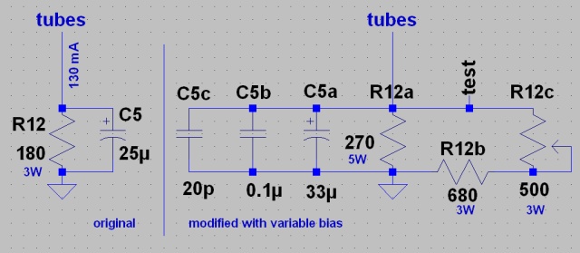 |
| Fig.36, on the left the original cathode bias circuit, on the right the one modified for variable R12 with which R values from 193ohm up to 220ohm can be obtained |
Today, almost all Quad II repairs mount a 200ohm 5W for R12 in order to be able to fit modern valves without exceeding 130mA.
After a series of calculations, Fig. 36 shows us the R values required to remain within safe limits.
Bias calibration should be done according to the following procedure:
Never drill holes, bore, cavity, cuts on a historical object to be restored. Even to mount the variable bias we have to find a method to mount the potentiometer so that it is accessible without having to open the case.
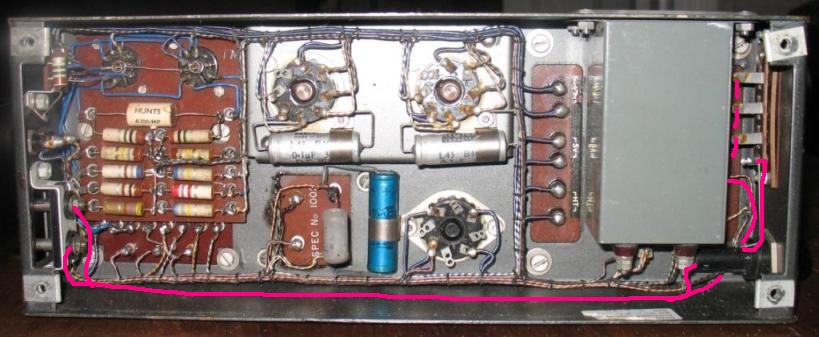
In fig.21 we notice in the lower left-hand corner a metal jumper which was used for the 220V supply, later used for a second set of binding post for biwiring, fig. 29.
 |
| Fig.37, the codes refer to the diagram in fig.36 |
The metal jumper was built new with a sheet metal so as not to puncture the original, and in Fig. 37 you can see the 3W potentiometer and the 2mm binding post mounted on the jumper.
Clearly we use top-quality components for R12b and R12c. To find the right values and quality, you have to leaf through half a dozen catalogues.
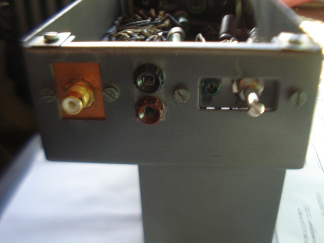 |
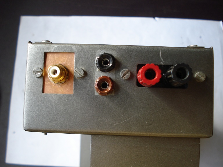
| Fig.38, here is the new front, from the left the RCA pin, the 2 output binding posts, the green test point pin, the potentiometer (all without modifying the chassis) |
There is no place to mount a panel meter (do we have to mention the Marantz 2, 5, 8b, 9 or almost all Tsakiridis again?) so a numbered knob would be useful to facilitate bias setting.
While waiting to find a suitable one we use a flat knob and a felt-tip pen.
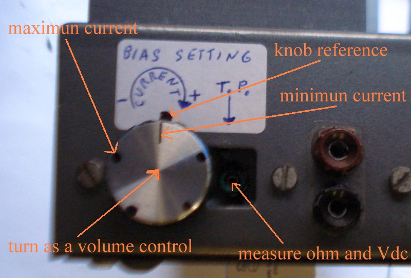 |
| Fig.39, not having numbers we use dots as a reference, in the picture some explanation |
To facilitate the task of those who will have to find the right setting for their KTxx we measure the ohms for some knob positions.
| Tab.5, ohms measured for different knob positions | ||
| position | n. xxxx1 | n. xxxx2 |
| Min | 219.2 | 220.5 |
| * | 214.2 | 215.6 |
| * | 208.2 | 209.1 |
| * | 200.9 | 202.3 |
| Max | 192.3 | 193.3 |
We can see the small difference between the two power amps due to the selection of components, buying 5 to find 2 similar ones, despite the fact that they are not 1% tolerance components (unobtainable in this case).
Apart from the measurements needed to test functionality, there is no time for other measurements (transient response, phase rotation, limit load curve, state transitions between classes A, AB1, AB2, etc.) the owner is chomping at the bit to get them back, perhaps after 1 year he is right.
| In the last years at Universita' Degli Studi di Roma La Sapienza |
Dr. G. Visco already contract professor for Chemistry in Environment & Cultural Heritage into --> |
Corso di Laurea in: Scienze Applicate ai Beni Culturali ed alla Diagnostica per la loro Conservazione |