|
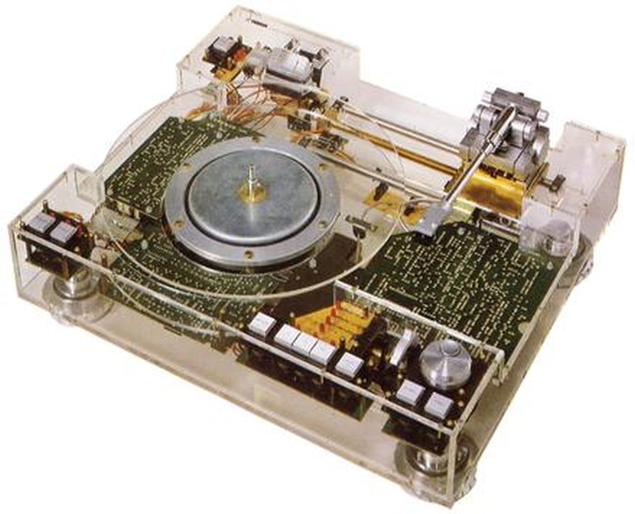
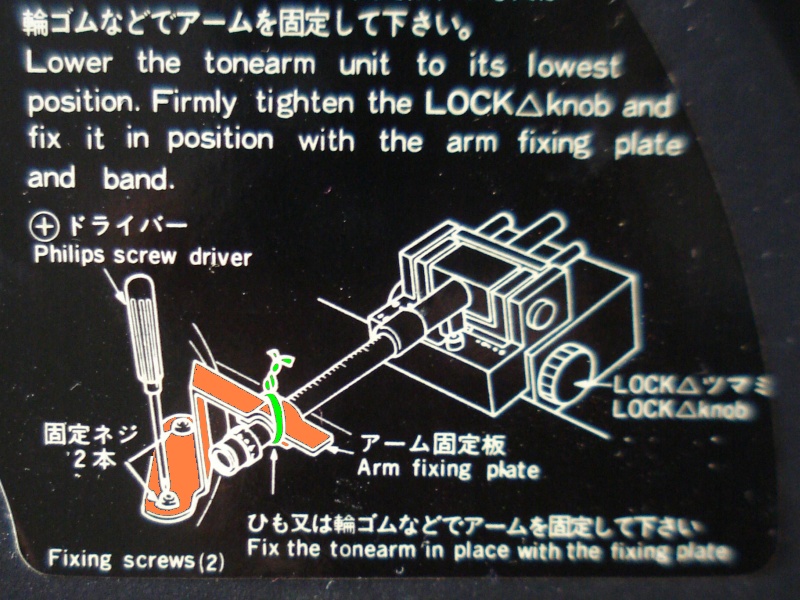
| Fig.108, inside the PX-1 (from audio-heritage.jp), our target for the upgrade of PX-2 |
All trademarks mentioned and links are presented here for informational purposes only and to confirm statements made by the author. The author of these pages DOES NOT receive any remuneration from the mentioned brands and the listed links.
In any case if you decide to use the suggestions on this page you do so at your own risk. Repairing electronic equipments, even just opening it, can put your life at risk, so don't do it.
If you do not accept and/or not understand the statements in this disclaimer, written in blue, exit from this page immediately.
Everything exposed in this web page is only a suggestion, probably you won't obtain the aim from you prefixed following it.
Be carefull, a true collector is looking for a) original items without any replaced parts, and with all accessories b) or if a Critical Restoration has been done that it is possible to go back to the original version.
A friend bought this "perfect" yamaha PX-2 used then realised that the arm moved little and badly, arm lift do not work, when run the cartridge rests heavily on the disc, no further test are possible.
The first thing to do was to repair, restore, the turntable, test all its functions, do all the necessary calibrations, maybe even listen it in comparison.
During the restoration, having found eighteenth defect, you understand how it works and whether there are design flaws or whether savings were made somewhere to reduce the cost of the PX-2. A few "cuts" can be remedied.
 |
| Here's what the late, renowned journalist and audio critic Giuseppe Moroni (known as Bebo) thought of the PX-1. It seems there are only two of them in Italy |
Let us analyse the most obvious design problems and see if they are solvable.
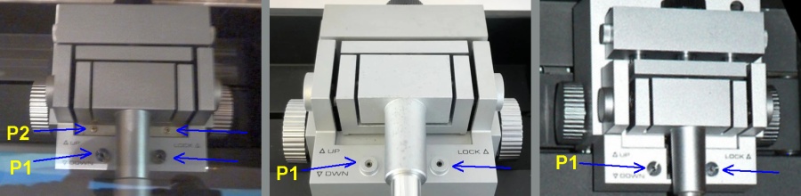 |
| Fig.109, there are at least 3 different arms mounted on the PX2. The coloured arrows indicate the differences. See the difference on P1, one is missing screws (fixed from below?), what do P2 screws fix? only one has them. Enlarged photos, Arm no.1, Arm no.2, Arm no.3 |
Different arms (even thinking about the PX-3) means different calibrations and some hidden settings? I don't think we will find anything in the copy, of the copy, of the copy of Service Manual that fortunately someone scanned.
Given the lacunae in the previous paragraph and some deficiencies on the previous webpage, here is the list of work to be done:
But before venturing into this challenge, let's try to estimate the cost. You have to build, drill, thread, disassemble all the PCBs, desolder, buy maybe 100 new components, just the MIL-compliant multi-pin connector for the external power supply costs a lot, the sound problem is difficult to solve, etc. etc.
A rough estimate can calculate an expense of 1000 euros for the owner if a real professional were to do it.
Tangential arms are complicated, difficult to maintain, delicate, but when they work they are unsurpassed for extracting information from a vinyl. Packing and transporting a turntable with a tangential arm is difficult and all precautions must be taken.
Clearly the seller does everything (if he is not dumb) to get the turntable intact from Japan to your home, i.e. when you buy a used turntable there must be the packaging with all the internal parts, not just the carton (yes already mentioned), here the 3 transport fixing screws are missing.
 |
| Fig.110, three new 10 mm, M4 type, 0.7 pitch, screws for fixing arm before transport. There was only one poorly secured parker-type screw so the original pitch is unknown but with an M4 (DIN933) threaded male the holes are very easy to touch up |
Having found the screws, we try to fix them in place.
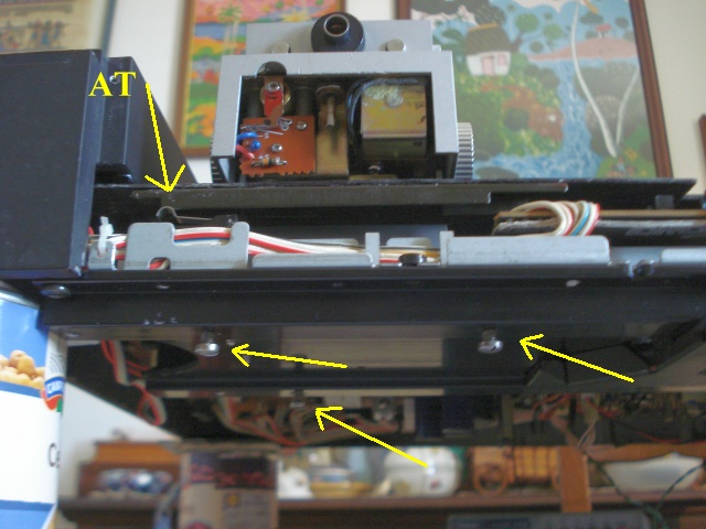 |
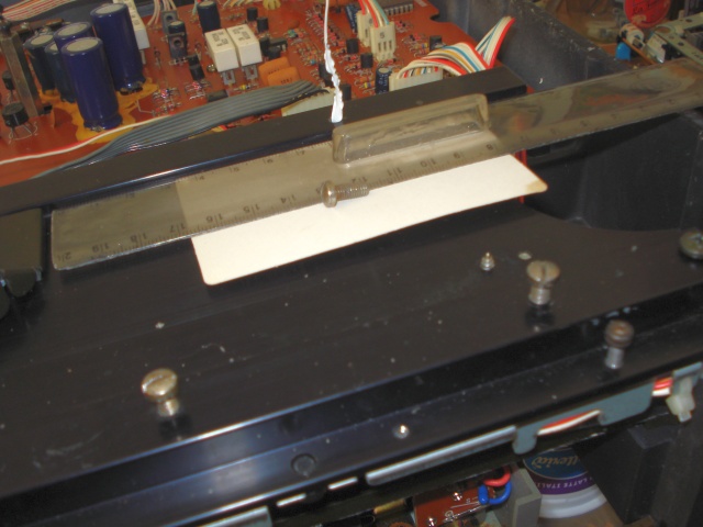
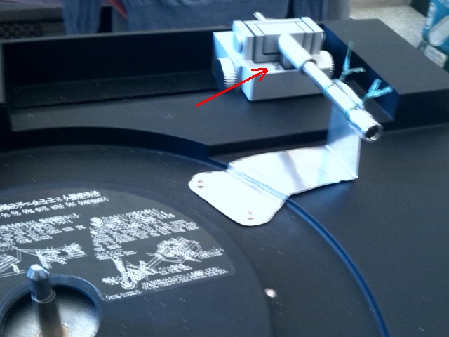
| Fig.111, put the turntable on 4 bean cans, run the arm until the right sensor is closed (see AT), tighten the 3 screws until the 2 rails are pressed together. DO NOT overtighten or the rails will be damaged |
Now it's time to look for a place on the turntable chassis to drill 3 holes, thread them M4, to park the 3 screws of fig.110 when not in use.
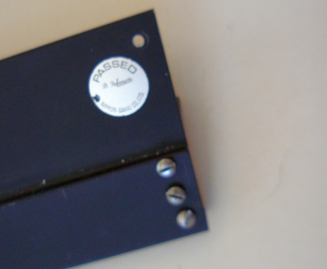 |
| Fig.112, the tonearm rear cover is a perfect place to drill 3 holes and leave the screw in parking, please check the rear space available before drilling |
You can see a hole above the Passed label. You can't see it in the photo but there's one just like it on the other side of the arm's rear cover, but more on that later.
This is a little piece of metal that is difficult to reproduce but INDISPENSABLE for securing the arm barrel before transport. At the factory they made a mold and with a press maybe make it in one shot but without even the original it's trouble.
 |
| Fig.113, in orange the metal tab that is MISSING, in green a lanyard used in the garden to tie up plants, with mouse hover you can se the original one |
Under the plate there are drawings to secure all parts before transport, one of these drawings reproduces the missing tab, in orange in the figure above.
Never buy a quality turntable like this unless all the accessories and all the additional parts that were in the packaging at the time of sale are present, never. If they are not there they indicate sloppiness, disinterest, carelessness, lack of affection for the turntable and disrespect for the buyer.
 |
| Fig.114, this is what you get with hacksaw, vise and bender, not pretty but it serves the purpose. Beware of the red arrow |
There are, embedded, two plastic inserts for small screws, we can recover 2 of them from some discarded printer with similar size.
Beware of the RED ARROW: the arrow points to one of the two screws that are on either side of the arm tube, they are NOT screws but position adjusters and MUST NEVER BE TOUCHED. They are not mentioned on any service and are used to position the arm at exactly 90 degrees in the UP position. Maybe I should have explained this in the calibration, sorry.
Let's go over the fig.2 on the previous page, 2 sub-weights are mentioned from the user's manual to balance heavy heads. These are also missing, we have to invent them.
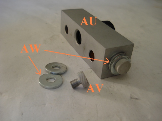 |
| Fig.115, AU= the original counterweight, AV= two counterweight screws, AW= two possible washers used as sub-weights |
By looking for high-density metal washers/squares you can get additional weights for about 10%. Of course being able to weigh the original weights would be better!
| Tab.5, counterweights obtainable without modification | |||
| with | metal | weight (g) | total (g) |
| counterweight | original | 140.7 | 140.7 |
| original screws | original | 1.0 | 141.7 |
| 2x squares 15x2 mm | gold | 16.8 | 158.5 |
| 2x squares 15x2 mm | lead | 9.8 | 151.6 |
| 2x squares 15x2 mm | brass | 7.8 | 149.5 |
| 2x squares 15x2 mm | iron | 6.9 | 148.6 |
For the table we assumed the use of two 15x15x2 mm blocks with 3mm hole, for more weight 18x18x2.5mm cubes can be used. In the green cells of tab.5 the obtainable weights almost without modification, useful for the next step, changing the effective mass of the tonearm.
Having two or three headshells is must, as you don't have to adjust the overhang and anti-skating every time. The adjustments are made using the AG template shown in Fig. 104.
 |
| Fig.116, on the lest the original headshell and on right a possible substitute the HS-2 |
There are only a few tonearms that allow the effective mass to be varied, mention must be made of magnificent pieces of engineering such as the Abis/Sorane SA-1 by Ishiyama-san, the Funk Firm F5, not forgetting the others, the famous Ortofon AB-309 12", the Audio Technica AT-1005.
A citation: the Ortofon AB-309 12" tonearm does not have a fixed effective mass, but is variable due to its different counter weights and the distance to the pivot point of the tonearm. It is one of the very rare tonearms with variable mass worldwide. A tonearm with variable effective mass, which makes it possible to use all cartridges with low compliance or with high compliance.
In forums and blogs there are, as usual, gurus and expert charlatans explaining everything about how wrong our arm/cartridge combination is.
Let's leave the charlatans to get excited listening to their empty words and have a look at 2 web pages that really try to explain the arm/cartridge system resonance (then we have to talk about the turntable and isolation with the room), let's read Ortofon and let's read Søren Iversen on Auditur.dk.
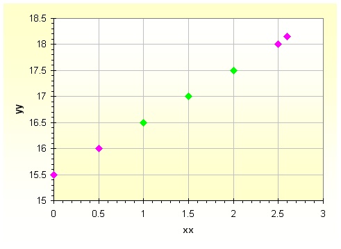 |
| Fig.117, from page 13 of the service manual we obtain the points in green, in purple the points calculated for other positions of the collar sliding on the arm tube |
We "built" an arm with a variable mass between 15.5 and 18.15 grams. For the weight of the cartridge ... we'll see in the next paragraph.
| Tab.6, variable mass tonearm values | ||
| slide position | effective mass | |
| 0.0 | 15.5 | |
| 0.5 | 16.0 | |
| 1.0 | 16.5 | |
| 1.5 | 17 | |
| 2.0 | 17.5 | |
| 2.5 | 18.0 | |
| 2.6 | 18.15 | |
Indeed, by changing the additional weights in fig. 115, or removing them altogether, other mass values can be obtained.
To set the cartridge weight we first choose the effective mass of the arm we are interested in, then position the cartridge along the shell slots as shown in fig.106 and fig.107 on the previous page, then adjust the VTA, finally do setting by turning the black counterweight knob.
Need I remind you that in almost every tonearm in the world you move the counterweight to adjust the weight of the cartridge?
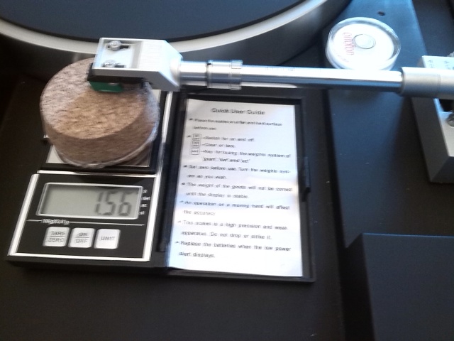 |
| Fig.118,top right the bubble for levelling, on the left a common digital scale (but check it with a 3g weight from your jeweller friend!), a cork of the right height equal to the plate+mat+disk |
Pictured here is a trick to use when using digital scales to adjust the weight of the head.
The better the cartridge, the stronger the magnetic field (in order not to disturb it, we use aluminium, brass, plastic screws) attracts the metallic scale plate, distorting the weight. Try it with and without the cork!
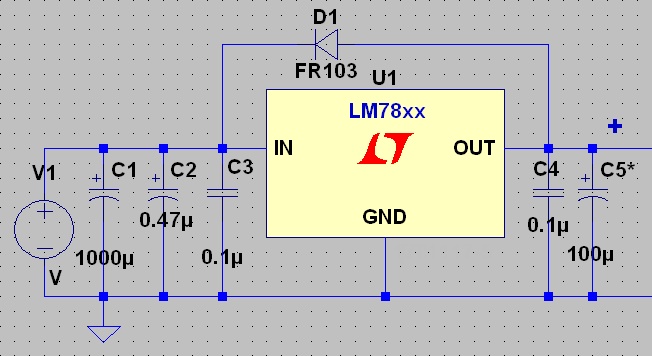
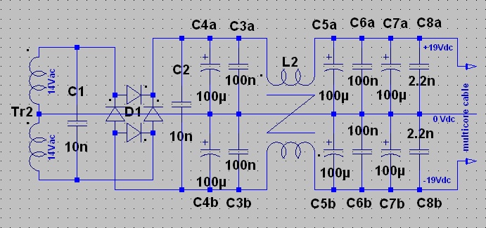
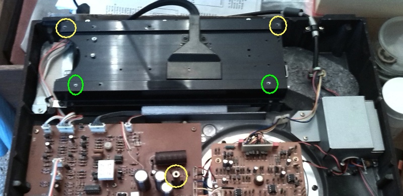
The arm lift circuit with its solenoid and other components as well as the entire motor control and drive circuit are powered by a single 24V stabiliser.
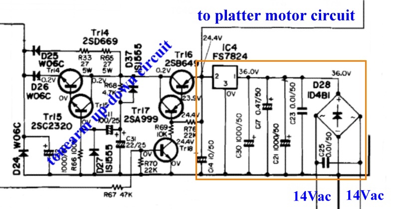 |
| Fig.119, in blue the two circuits of the platter's motor/control and the arm's control, in orange the 24V rectifier and stabiliser circuit that needs to be doubled |
There are not really two circuits to duplicate, orange rectangle, but only the two 24V voltage stabilisers are to be duplicated, having moved the transformers, diode bridges, and first capacitors outside.
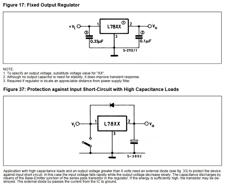 |
| Fig.120, from the original STMicroelectronics datasheet, 34 pages, we see how the 78xx series is really to be used. Above the capacitors for stability, below the bypass diode for large C output values |
C14 in Fig. 119 is NOT 10uF, but we find a 100uF fitted, hence the diode at the bottom of Fig.120 (fig.37 protection against ...) is really needed. An FR103 is sufficient. Always find and look for the oldest datasheets in modern ones often missing pages and pages.
C17 of 0.47uF is fine but 0.1uF is missing at the output and on other datasheets it is recommended, ceramic, also at the input, add it.
There are three 78xx-series stabilisers in the original circuit, IC4=FS7824, IC5=FS7812, IC5=NJM78L08, plus the other IC4b=7824 which we added for the motor only. To all we apply the sum of circuits of fig.120.
 |
| Fig.121, this circuit will be used for all PX-2 stabilisers, only for the LM78L08 the C5 value is reduced to 22uF |
By reusing the PCB of the power-on circuit, we can build the second 24V power supply for the platter motor on it.
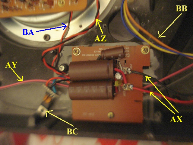 |
| Fig.122, new separate 24Vdc stabiliser for the platter motor. AX= the 38Vdc from the external supplier, AY= two wires from the remote power on, AZ= pass through 38Vdc for the tonearm PCB, BA= 24Vdc for the platter PCB motor, BB= 19-0-19 Vdc from the external supplier for the tonearm PCB, BC= LM7824 added. Mouse hover to see other side |
Having understood "how" voltage stabilisers are to be used, we move on to the construction of the power supply.
Not only a new external power supply, but having to build it, we redesign the circuit according to modern standards (C-L-C in common mode, separate ground, centre tap ground, EMI filter, e.g.)..
Earth or not?
The original turntable has no earth on the power plug. It's not the only one, almost all turntables are built this way, think of Thorens, Garrard, Rega, the earth is on the preamplifier (maybe) and is distributed through the RCA pins or through a dedicated earth wire.
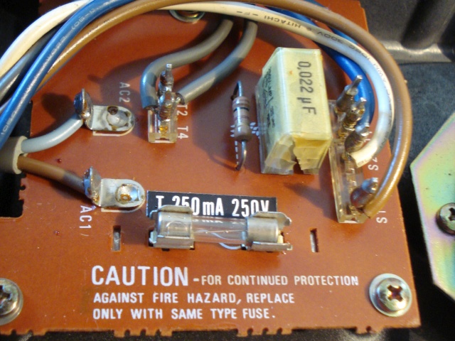 |
| Fig.123, on the left you can see the power cable, AC1 and AC2 just two wires. The PCB is disassembled and reused see figure above |
If you build an external power supply, with a metal case, this will have to be grounded to the mains. To respect the original design, only DC voltages were passed from the external power supply to the turntable, not the earth.
Electromagnetic interference (EMI), electromagnetic compatibility (EMC)
Today, all electromedical and measuring instruments have RFI, EMI, EMC filters due to the complexity of the modern power grid and the excessive presence of electromagnetic pollution. With a click on the preceding acronyms you can see some explanation.
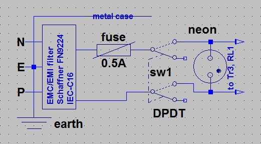 |
| Fig.124, we bring 230V into the new case with one of the best EMI filters, double switch, fuse and neon lamp |
Let us immediately show the result, the rear side of the case with the components in fig.124 mounted. One small problem is making that rectangular hole!
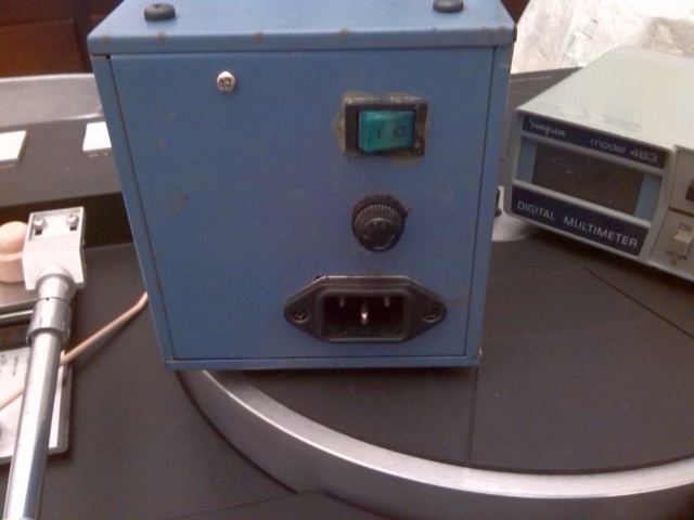 |
| Fig.125, external power supply, rear side, see the IEC socket with encapsulated EMC/EMI filter, above the fuse and again above the double switch with lamp |
Remote power-on
The turntable originally had the power switch inside, whose spikes also destroyed the 0.022uF (spark-killer) capacitor in fig.123.
By taking the two transformers outside and also taking the rectifier circuit outside, it would be stupid to still circulate 230V inside the turntable. That is, you have to build a remote start with the 12V switch.
 |
| Fig.126, design of the remote switch-on circuit with relay and only 12Vdc inside the turntable |
Let us describe the purpose-built circuit in more detail:
 |
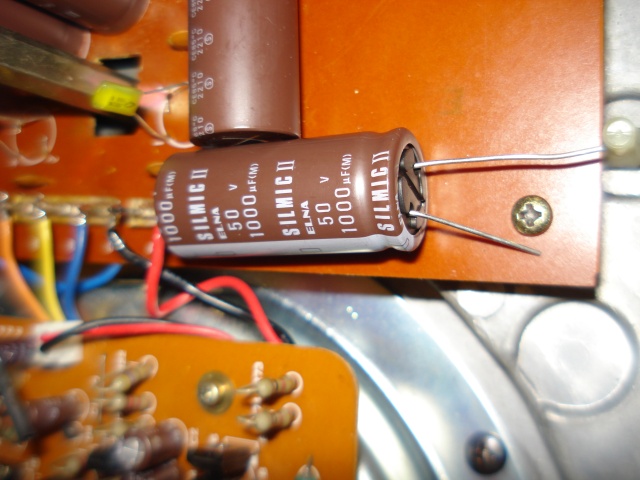
| Fig.127, realisation of the remote ignition circuit, the labels refer to the circuit in the figure above (yes C1 is also a Silmic-II !) |
New external supply
To power the turntable there are 2 different voltages, and also 2 transformers as seen on the left of fig.10.
On the arm's mainboard are the 2 rectifier circuits and the stabiliser circuits. One produces -12-0+12V and the other 24V.
To build a new external power supply, it is best to reuse the original transformers (excellent, well-built, well-shielded and oversized) while redesigning the rectification/filtering circuit according to more modern, and more expensive, standards. We have already talked about stabilisation, we will follow fig.121.
The single 38V supply
We partially recover the design of the original rectifier with the 10nF before and after the diode bridge, but add a common-mode filter inductance with the secondary capacitors of at least twice the value of the primary ones.
We also add the 100nF used today in each rectifier circuit and 22nF at the output as an EMI filter.
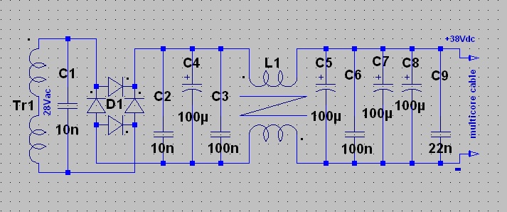 |
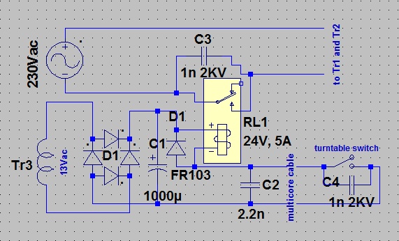
| Fig.128, the new rectifier and filter circuit. We use oversized components such as the 4A 400V bridge, the 2A choke a specially designed PCB |
Build the PCB
Before constructing the PCB, let us read the considerations on a previous page of mine analysing the disastrous tendency to build wrong PCBs, in current.
In an earlier project, Magnum MF-125, we see in Fig.18 a PCB constructed as it should be in high currents.
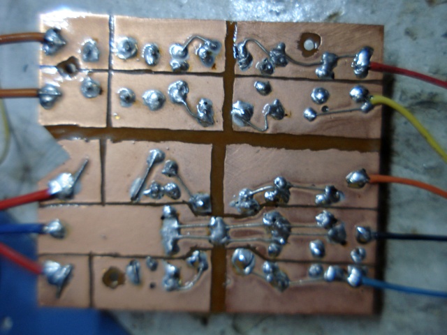 |
| Fig.129, the hand-made PCB, solder side, with component's wire used as fortifier. Above the 38V section, below the +19/0/-19V section |
As already seen on the previously mentioned web pages we use a 2 oz/ft2 copper and remove with the Dremel only 1mm of copper to separate the tracks.
The PCB is designed to: minimise the series resistance of the circuit, keep all positives and negatives floating, leave the ground floating from the chassis, reuse the original transformer wires.
The +19 0 +19 V supply
Also for this design we partially recover the original circuit with one rectifier only and with the 10nF before and after the diode bridge. Of course we add a common-mode filter inductance with the large secondary capacitors.
 |
| Fig.130, new dual rectifier and filter circuit. Also with oversized components such as the 2A/200V bridge, the 2A choke a specially designed PCB |
In order to minimise interference between the inductances, we need to find 2 inductors with different construction so that when fixed on the PCB they have their cores at approximately 90 degrees to each other.
Case and circuit
We need to find a case that is large enough to hold all the circuits seen above and the two transformers, perhaps leaving some space for ventilation. It must be metallic for shielding and "remember" of the PX-1 case.
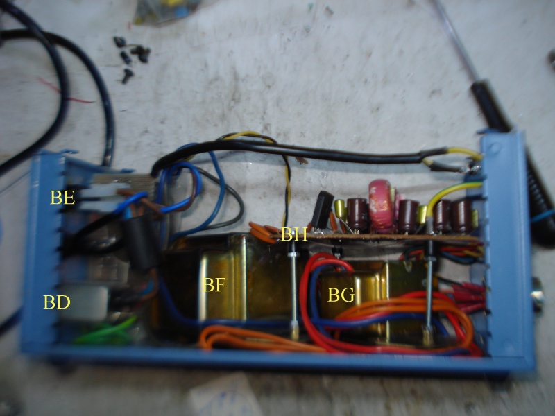 |
| Fig.131, let see: BD=EMI filters inside IEC socket, BE=double switch with neon lamp, BF=28V transformer, BG=19-19V transformer, BH=new PCB |
Below is a photo of the interior with the new PCB in view with the components mounted. The chokes have been dipped in wax to reduce vibrations. You can see various yellow/green wires that connect the IEC earth to various points of the case (but no part of the circuits).
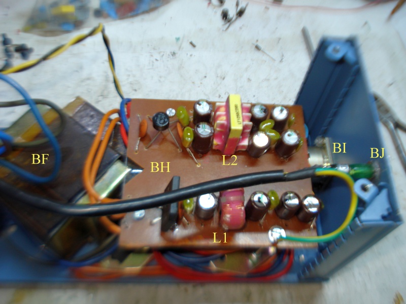 |
| Fig.132, BF=28V transformer, BH=new PCB, L1 and L2 the two different chokes, BI=7-pins 5A/250V military-type connector, BJ=neon lamp light on when volts are present on BI |
At last we see the external power supply finished and closed. We do not change the original, indefinable colour.
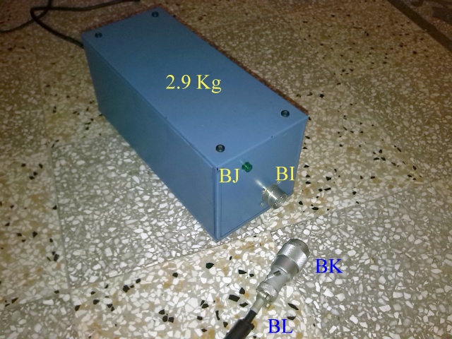 |
| Fig.133, the external power supply for Yamaha PX-2 finished, see BI=7-pins 5A/250V military-type female connector, BJ=neon lamp light on when volts are present on BI, BK=7-pins male connectors, BL=ferrite tube (reuse from CRT monitor cable) |
Inside the turntable
By moving the transformers outside, there are also several changes to be made inside the turntable.
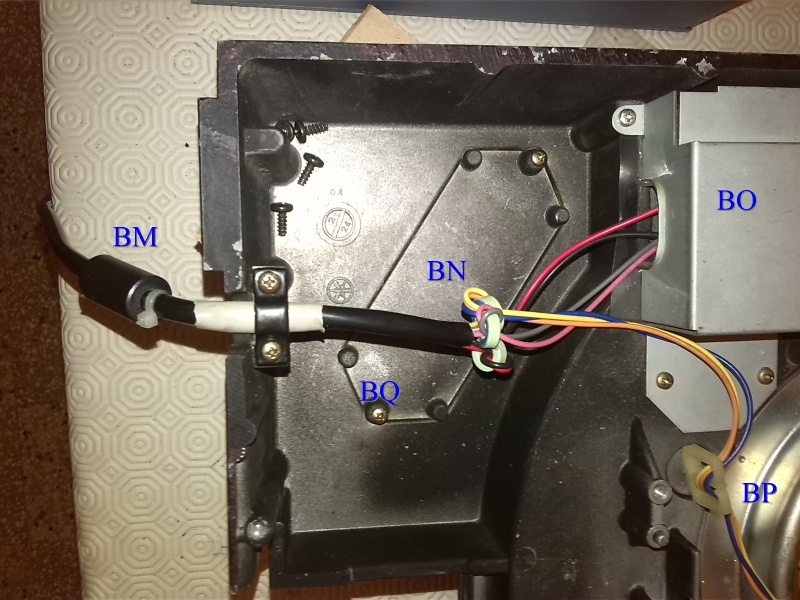 |
| Fig.134, in the photo the arrival of the cable to the turntable, note: BM=another ferrite tube as BL, BN=3 ferrites on each cable pair, BO=the filtering cap. for 24V, BP=the cables to the 19-0-19V filtering cap., BQ=screws to be used to fix the additional weights |
In the previous photo BO covers the filter circuit with the two 1000uF capacitors shown in fig.122. Below is the new 24V stabiliser for the platter motor only.
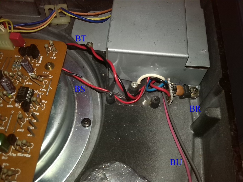 |
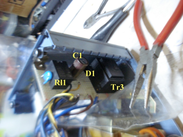
| Fig.135, in photo, BR=new 24V stabiliser, BS=the new cable to the motor PCB, BT=filtered 38V cable from fig. 133 to the arm PCB, BU=cable to the power \on switch with only 12Vdc |
An outline plan, or better a canovaccio, was followed to build the external power supply, but there were several modifications along the way, so only at the end we see what we got, see below.
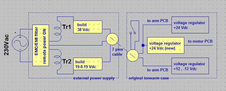 |
| Fig.136, the block diagram of the complete power supply circuit, in yellow the new circuits but the others have also been updated as shown in fig.121 |
Built the external power supply and updated the filter and stabilisation circuits the turntable works (it also worked at the end of the restoration) but more can be done.
What are the best electrolytics for Audio? If you ask this question in a Blog or Forum you will start furious disputes that can even result in real insults and personal threats. Here instead, after so many years of restoring wonderful preamplifiers, amplifiers and CD players, the answer is already there: they are the ELNA RFS Silmic II.
 |
| Fig.137, a Guru statement, from https://www.diyaudio.com/community/threads/best-electrolytic-capacitors.151392/ |
So let's just use those, yes even in the external power supply! It sounds crazy but it can't hurt.
Discontinued? Yes! As Rubycon Black Gate, Elna Cerafine and some other best capacitors for audio.
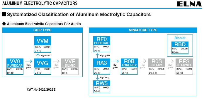 |
| Fig.138, in gray the discontinued series, no suggested substitute from ELNA, from https://www.elna.co.jp/wp-content/uploads/2022/11/catalog_22-23_E.pdf |
But WE HAVE A PROBLEM, for branded audio components there are hundreds of fakes around, the more famous they are, the more fakes there are, we have to find a reliable supplier.
Change capacitors
ALL electrolytic capacitors are replaced with Elna RFS Silimic II. Everywhere, in the new external power supply, in the 2 PCBs, and even the tantalums are replaced with ELNAs, given the reduced space only C36 remains in place.
 |
| Fig.139, an example of the replacement of capacitors with Elna |
By changing all capacitors, we also update the stabilisation circuits as shown in fig.121, see below.
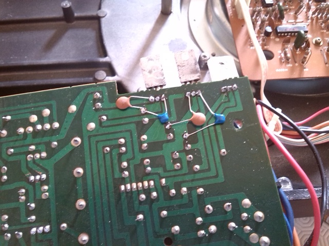 |
| Fig.140,the two ceramic capacitors for each of the 78xx stabilisers |
Here is the final result for one of the 2 turntable PCBs.
 |
| Fig.141, the tonearm control PCB with all capacitors replaced |
Since we have to completely disassemble the 2 PCBs to replace the capacitors, we can go further with the upgrades.
Change solder
The solder is also 30 years old and some might give us problems in the future, so better to replace all the tin (using the appropriate tools to avoid damage).
NEVER mix old tin with new. Each alloy is built around an eutectic point to achieve the necessary mechanical and electrical properties. The old tin must be completely removed with an air desoldering pump and perhaps then passing it through the solder wick.
During testing, the Quartz Locked led would sometimes flash as if the motor had lost its 'lock'. Having to redo all the soldering, we started from here.
 |
| Fig.142, by enlarging fig. 87, we can see the flaws in the soldering of the flat cable, top. In contrast, the soldering of the coils, bottom, is very good. |
To rebuild the solder, each component must be desoldered and after removing all the old tin, re-soldered.
 |
| Fig.143, EVERY component is desoldered, measured (replaced if necessary) and then re-soldered |
To measure ALL components one by one and not make errors and/or omissions, we use an already known technique:
*Everyone is good at desoldering, but soldering is a mix of art, craftsmanship and science. Unfortunately, audiophiles have a tendency to kill themselves with chatter without scientific basis, but if you want to know a bit more, read Mark Philpot's comments at this good video, or read 2 application notes from one of the most respected "Tin Alloy" manufacturers, Comparison tin silver copper vs lead free alloys, or Reflow profiling time above liquidus, how to. But were we talking about welding or brazing or soldering?
Although it did not look like it at first glance, we must state that the components used were EXCELLENT, both R and C. The quality of the turntable is confirmed.
Having completed the measurements, we can say that the brownish-coloured Philips resistors (the model with the painted rheophores) are very good, after more than 30 years they are within 2% error. On the other hand, all the capacitors were within 10% of the nominal value, a very good result.
This corroborates a statement found on some website of the world's best technicians: "ORIGINAL COMPONENTS ARE NEVER CHANGED, THEY ARE DISASSEMBLED, THEY ARE MEASURED AS WELL AS THE BEST, AND THEY ARE REASSEMBLED ALSO TO KEEP THE SOUND PATTERN OF THE EQUIPMENT".
Add socket
Having disassembled the PCBs, we put all the ICs on socket.
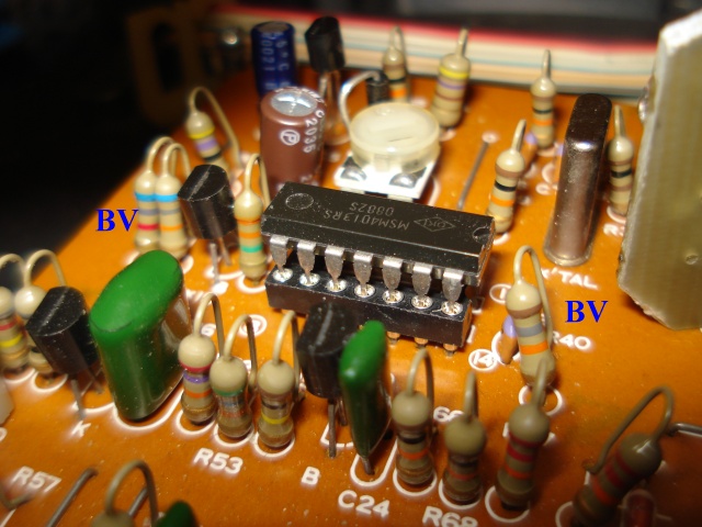 |
| Fig.144, the best sockets for every integrated circuit. BV=the good quality Philips resistor |
The operational amplifiers are all replaced with new JRC 4558Ds, see bottom of fig.143. For all other integrated amplifiers, the original or an equivalent is sought, installed for testing and set aside for solve a future failure.
In searching for replacement integrateds we discover a devastating problem. Let's call it the nineteenth defect, the Yamaha YM-294 integrated amplifier (a Logic System Integrated circuit, see fig.101) is nowhere to be found, worse still, there is another LSI, again a Yamaha with the same initials but a very different case!
 |
| Fig.145, all sockets installed on the motor PCB, on the left we see the 2 red Wima in place of the non-polarised electolitics originally present (and NOT mentioned in the service manual, and not present in the new versions, cost-cutting?) |
Of course after installing all the sockets, all the capacitors and redoing all the soldering a long test is necessary, if it passes ....
Given the tortuous cable path between the shell and the RCA output cables, better to change everything to a very good tonearm cable, Cardas 4xAWG33.
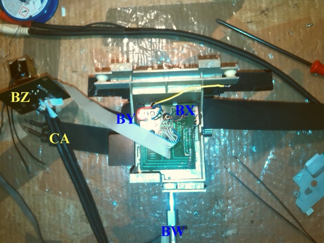 |
| Fig.146, we follow the tortuous signal path from the cartridge to the RCA pins. BW=4 wires from the connector to the first PCB, BX=4 wires + 2 blacks end up in the PCB, BY=a computer flat cable uses 5 conductors for the signal, BZ=the flat is soldered to the second PCB, CA=finally the signal arrives in the RCA cable |
A sensitive point is the passage in the PCB under the tonearm, let's zoom into that point.
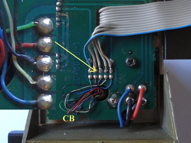 |
| Fig.147, to the 4 coloured wires add 2 black wires in the centre, one for the tonearm barrel ground and one for the horizontal pivot pin. CB=a fused plastic pin as a retainer!!! Then there will be a screw like the one in the photo |
Passing the new cable
Usually you disassemble the block that holds the headshell, pull it off a little, desolder the wires, solder the new wires to the old ones and then start pulling from under the arm.
This procedure works once yes and a no. If the arm tube is damped and the path in the bearing zone is not linear, the method does NOT work, and in fact it is not useful here.
If the arm wiring has to be replaced, it is better to disassemble the arm in all its parts and do "maintenance", but it is a highly discouraged job only some experts can venture into this nightmare. Take lots of photos as you disassemble.
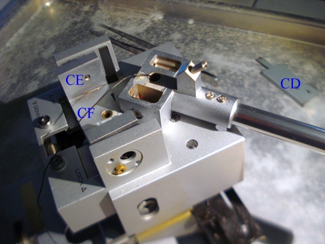 |
| Fig.148, it is strongly discouraged to disassemble the armtube, consult a specialist. Of course in this case is necessary, here is the arm disassembled for re-wiring, CD=a tool specially hand-made for disassembling the bearings, CE=maybe you can see the cone screw that holds the bearing, CF=the ground wire of the arm tube |
After disassembling everything (but NOT the pivot pin) we arrive at fig.148. Once the barrel and bearings are disassembled, it is easy to pull out the old rows and pass the new ones, but you have to be careful about the route of wires.
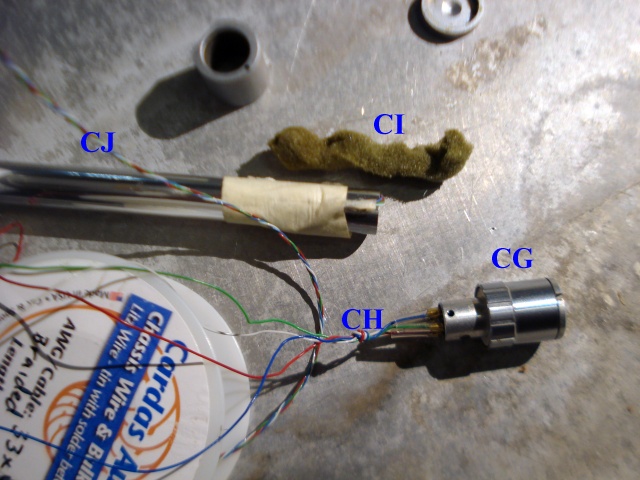 |
| Fig.149, there is a screw to be removed to detach the shell locknut and then everything can be pulled off, CG=fixing nut and holder for headshell, CH=the old wires with a knot, CI=the barrel damping, CJ=the new Cardas 4x33AWG, Teflon wires, twisted |
We run the new wires taking care not to damage the 2 black earth wires.
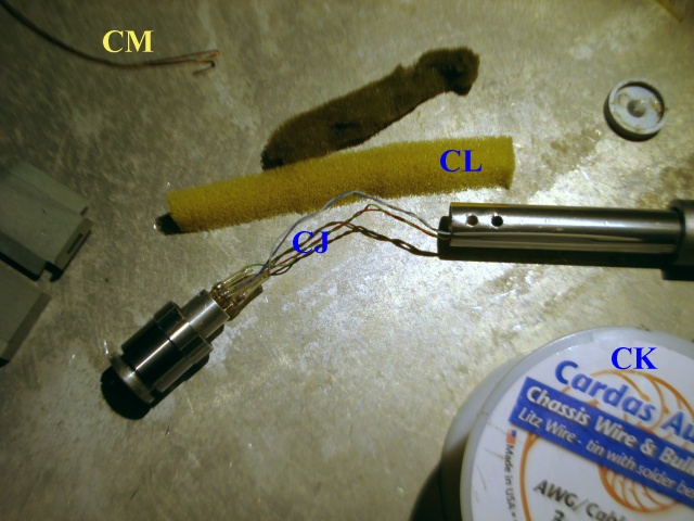 |
| Fig.150, new wires for tonearm, CJ=the new wires but without the knot, CK=the Cardas spool, CL=the new foam, the dumper, CM=a solid core wire to help fit CL |
After 30 years, the foam, CI, which acts as a resonance damper on the armtube is also looking too good, but having disassembled everything better to replace it with CJ, which should be distributed in the centre of the armtube.
 |
| Fig.151, the barrel with the new wire and damping foam, note the headshell fixing collar and the copper nail. When soldering the wires, it is best to keep the headshell mounted to dissipate heat on the pins. |
Care must be taken when fastening the headshell collar screw and ground continuity.
 |
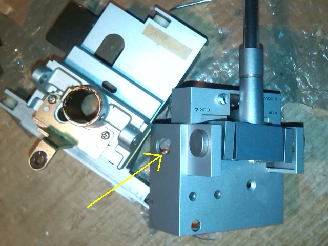
| Fig.152, the difficult tightening of the bearings, or rather the cones that fit into the bearings, with a specially constructed tool, CD of fig.147 |
Reassembling the bearings (CE of fig.148) is not easy. It would be too complex to explain here and you would need 10 more photos but ... if you have calibrated with a feeler gauge the valves of an old Ducati or Royal Enfield with lifters, pushrods and rockers, now think 1/50 scale and you can do it.
 |
| Fig.153, the frame on which the horizontal pivot pin is fixed. We see the black plastic block which controls, by tilting, the dropping of the arm |
All the movement mechanisms of the arm are now completely disassembled in all their parts, hopefully remembering how to reassemble. Let's see it step by step.
 |
| Fig.154, Let's start by reassembling the infamous arm-drop-damping system (which grease must be used?). |
In fig.154 the brake lowering system of fig.66 reassembled, now it is easy to see it and you can also understand how it works.
We now reassemble the solenoid, paying attention to the positioning of the load spring.
 |
| Fig.155, at the bottom of the picture we see the remounted solenoid, always take care to not damage the thin arm wires |
Now it would be best to test the system by feeding 16 or 17 Vdc to the two black wires of the solenoid (just a few seconds) to test the movements before fitting the "second layer".
 |
| Fig.156, on the right is the first of the frames we reassembled, on the left is the frame with the rails still to be reassembled. |
The arrow in fig.156 shows the pins on which the black plastic block in fig.153 that governs the arm descent rotates, better a drop of oil before reassembling everything (you can see better the fixing nut in fig.148).
Remember that on the brass stud in the centre of fig. 154, the spring that pushes the two frames apart must be put back on.
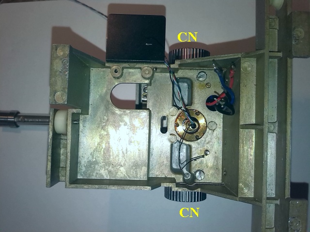 |
| Fig.157, the two knobs, CN, that are used here to hold the second frame in place until we reassemble the other parts and then serve to adjust the VTA |
Now comes the tricky part, reassembling the optical/mechanical system that is used to monitor the arm's movements horizontally.
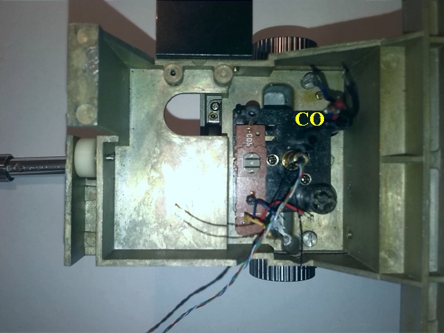 |
| Fig.158, with CO we see the plastic frame, attached with 2 small screws to the fixed pivot of the arm, which holds the CDS sensor |
Now reassemble the optical system attached to the arm pivot pin, which with its slot interrupts the light beam hitting CDS.
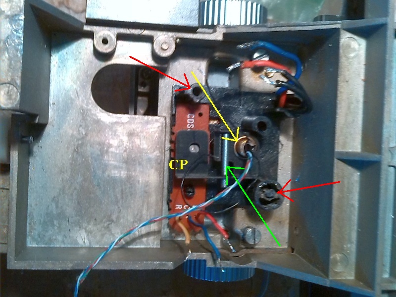 |
| Fig.159, with CP we see the mechanical assembly which is fixed with an Allen screw on the pivot pin. The green arrow shows the endless screw (never documented) for adjusting the position of the CP hole in front of the CDS. But who is the genius who thought of holding the whole PCB going up here with just a screw, in plastic, and a ridiculous pin also in plastic, see red arrows? |
In fig.159, the yellow arrow indicates the height of the CP frame on the pivot, an important position for setting the correct shadow cone on the CDS sensor.
Absolutely without any indication in the service manual you can only measure and photograph the original position before disassembling the arm.
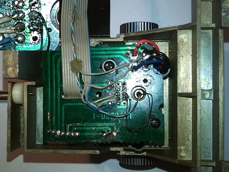 |
| Fig.160, The last PCB is also assembled, we see on the right below an added fixing screw. On the flat cable the Cardas wire has been glued in several places, in the top left detail the two black ground wires now use 2 wires from the flat cable for connection |
The flat cable must remain to carry the various signals to the arm, we also use it as a holder for the new wires. To reduce the resistance of the grounds and bring more current to the solenoid, we reuse the four wires of the flat cable that are now left over.
Having fitted a new cable for the arm, we have freed up five wires from the flat cable, leave the blue one as index1, use no.2 and no.3 to connect the two black ground wires of the arm, use no.4 and no.5 to duplicate the wires carrying current to the solenoid (the rebuilt one).
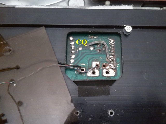 |
| Fig.161, the board from which the old arm cable, the Mogami, originates and which also serves for the calibration of the arm position and for the power supply, in CQ you can see the thin added cables that go up to pins #3 on the mainborad, see also the 4 Cardas wires and the black cable for ground |
Doubling the solenoid cables requires an added connector on socket #3, but without disrupting the design.
Many turntables have a removable output cable, i.e. they mount a pair of female RCA pin-jacks to which any cable + ground wire can be connected.
We don't have to get into a discussion about "connection cables" at all, as everyone will keep their own ideas after arguments, injures and insults. But let's give the possibility of using "any" cable to the PX-1.7.
Maybe some users can also keep the excellent Mogami Neglex 2496 interconnection cable, 2710 AWM Vw-1 phono cable used by the PX-2, just add two good male RCA jacks on the side that was soldered to the turntable.
With a caliper, we take good measurements of the space where the cable was fixed, fig.11 and fig.13, and design a Poly-methyl methacrylate (PMMA, Plexiglas) mounting plate, also thinking where to mount the RCA jacks.
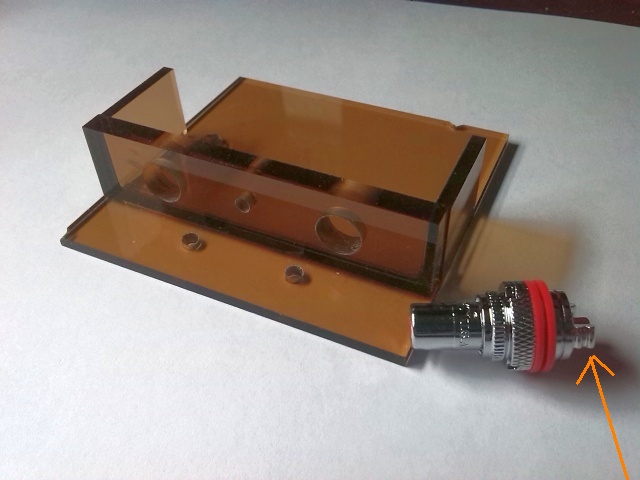 |
| Fig.162, the finished PMMA board, notice in front the 2 fixing holes that reuse the screw holes of fig.13. On the right we see the suitable connector given its long, long threads, the Charming Music Conductor CMC-805-2.5-CUR-RH, here is a dealer |
Now the output cable must be desoldered, see fig.85, and using the two screws already present, fasten the new board.
The two parker screws securing the PCB in fig.13 protrude from the chassis and leave a mark on the PMMA board. With these marks, two 3mm holes can be drilled in the PMMA board.
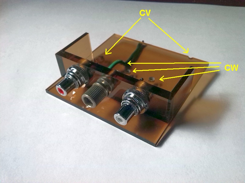 |
| Fig.163, the board with the RCA jacks mounted and in the centre the binding post for the earth. Note in CV the additional fixing holes (see text) and in CW the holes for the arm wire routing |
Looking at fig.11 only one of the parker screws has to be removed (on the left) and a 3mm through-hole drilled in the chassis. Now a 3x15mm bolt with nut is used to secure the PCB. Then the other screw can be removed and 3mm hole can be drilled to secure the PCB with a new nut and bolt.
The two 3mm bolts should (we hope) pass through the holes already drilled in the PMMA base, see CV of fig.163.
The fixing of the board is a delicate step: one must not damage the PCB by over-tightening the bolts, but the board must be firmly fixed, and the two original parker screws fixing the old black frame are too short.
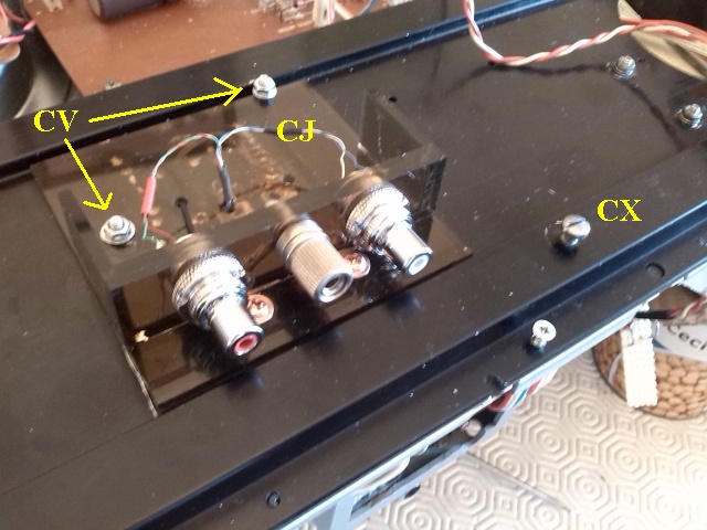 |
| Fig.164, the new PMMA base plate attached to the arm frame. We see the CJ the Cardas wires, CV through-bolts reusing the holes already present. Crucial is the use of the 3 transport bolts, CX, to secure the arm during all drilling operations. In the upper right the white-red cable connect to |
Soldering the two CMC-805's is not easy, before mounting them with a fine file you must prepare the soldering area of the ground, orange arrow of Fig. 162, and then solder on this spot leaving a drop of tin. After mounting the RCAs on the PMMA, it will then be possible to heat up this drop of tin and connect the already tinned Cardas wire without melting the methacrylate.
In the design of the base plate, an attempt was made to make it as low as possible so that by unscrewing the original feet by a couple of turns, it would NOT touch the base surface.
Once the wiring with the new Cardas cable is finished, there would be a need to take capacitance and resistance measurements as per table 4 to look for differences.
Aside from the endless arguments about who is right (the one who shouts the loudest and who can beguile the best), on the various forums, if you buy a professional shielded cable, you will find a world of measurements in the technical data sheet, more than just the capacity, but the howling audifiles cannot explain any of them, so they insult you on the capacity alone between conductor and ground.
| Tab.7, capacitance as see the cartridge using new Cardas cable up to the new female RCA | |||||
| picofarad (pf) | L wire | L shield | R wire | R shield | ground |
| L wire | 0.69 | 27 | 2.8 | 3.4 | 28 |
| L shield | 27 | 0.72 | 3.4 | 3.1 | 30 |
| R wire | 2.9 | 3.3 | 0.70 | 28 | 29 |
| R shield | 2.3 | 3.1 | 28 | 0.67 | 31 |
| gnd wire | 29 | 30 | 29 | 31 | 0.35 |
We maintaining the excellent phono cable used by the PX-2, Neglex 2496 interconnection cable, 2710 AWM Vw-1, and do all possible capacity measurements as suggested by the figure at the bottom right of Mogami's webpage
The Mogami catalogue is a huge source of information that many audiophiles overlook or don't know at all, maybe start reading from page 74 onwards.
| Tab.8, capacitance as see the cartridge using new Cardas cable and original RCA cable | |||||
| picofarad (pf) | L wire | L shield | R wire | R shield | ground |
| L wire | 0.85 | 135 | 57 | 88 | 73 |
| L shield | 128 | 0.78 | 80 | 168 | 131 |
| R wire | 62 | 82 | 0.80 | 142 | 100 |
| R shield | 82 | 171 | 134 | 0.82 | 204 |
| gnd wire | 74 | 120 | 87 | 184 | 2.27 |
Replacing the arm cable produces different values in the measurements, all capacities are increased.
So much effort to disassemble the tonearm bearings, reassemble the bearings hopefully tightening them properly, redo all the wiring, finding ways to hold the Cardas in place to get Worse Results in terms of capacity and resistance (but WHO ever does these measurements before and after?). Maybe the sound will be better, we hope.
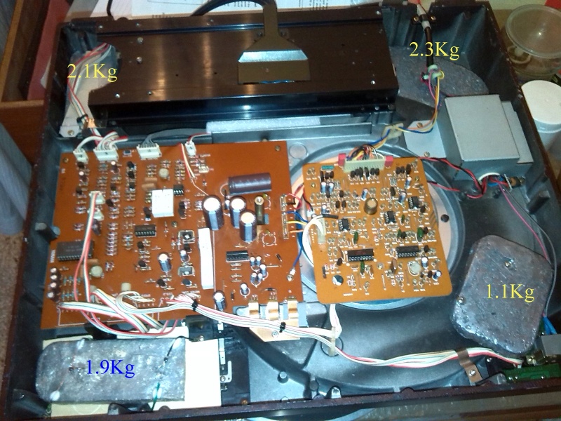
Let us review fig.7 and table 1 on the previous page. The unbalance on the support feet worsened after removing over 2 kg of transformers and other modifications.
But by removing the transformers we have recovered space for a number of additional weights, which, however, must be carefully shaped and positioned. The final goal is to exceed 20 kg in total with a maximum unbalance on the feet of 1/2 kg.
Trying to balance to the gram is pointless as the arm with its carriage when moving moves its weight over the 4 feet differently.
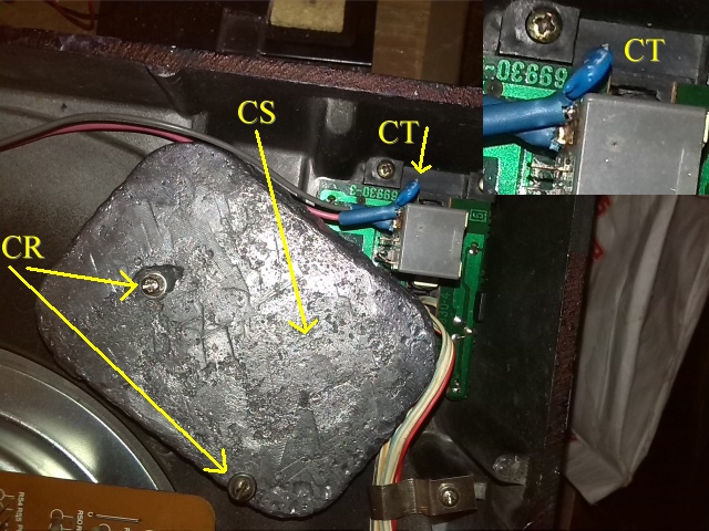 |
| Fig.165, the weight under the ignition switch, 1.1Kg, CR=the two through screws using 2 threaded turrets already present, CS=a parker screw using a hole already present on the chassis, CT=spark killer capacitor on the ignition switch (although we only have 13V here) |
To build the additional weights we use an alloy of lead and antimony (Pb98Sb2), often used in thermal hydraulics, "When antimony is mixed with lead, the lead becomes firmer and harder. It is unreactive, resists oxidation and corrosion in most environments, and forms a protective, impermeable film faster than pure lead". The alloy used here show a melting point of around 350 degrees. The moulds are made from various metal cans found on supermarket shelves, tuna, salmon, sardines, sturgeon, etc.
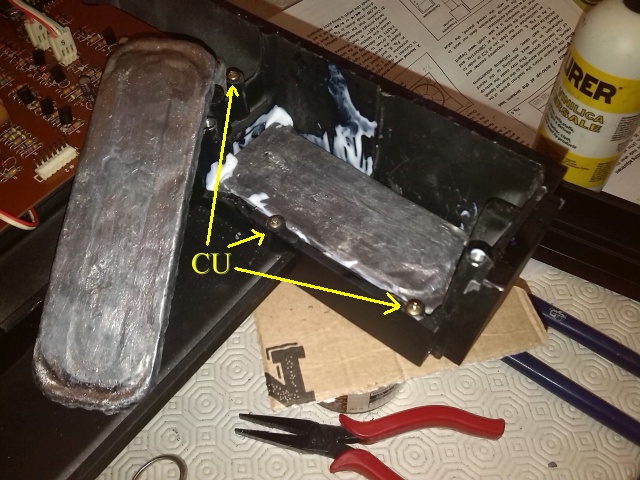 |
| Fig.166, the top right-hand corner, there are no fixing points so 3 turrets have to be drilled and threaded and an anchor frame constructed, CU=3 parker screws screwed onto the turrets |
Each corner has its own problem to fix the additional weight, the worst point is the right rear corner, there would be a lot of space but partly occupied by the castle with the pulleys and by the flat belt of the arm.
 |
| Fig.167, with some difficulty all the additional weights are well secured |
Once the work is done, it must be pointed out that melting lead is dangerous. The melting temperatures are dangerous, the fumes produced are dangerous, casting in moulds is dangerous, and casting recycled metals is even more dangerous. You need a foundry, never do these operations at home or in the garden.
The bottom cover is made from a heavy sheet metal stamping, better than many others, but the sheet metal is only painted.
To dampen a sheet metal lid such as that of this turntable (but also the lid of a CD player, or a pre-amp) you need something that remains 'soft' over time, does not become glassy, is well adhered to and easy to spread. A good result can be achieved with waterproofing resins for terraces.
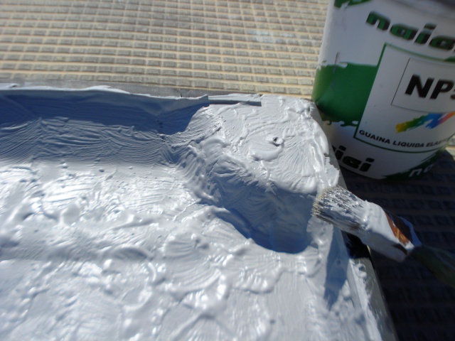 |
| Fig.168, an old brush and a slightly random application for a better result |
We do NOT get an euro by advertising, but we must at least mention the product: NAICI NP5 is a versatile easy to use liquid resin membrane. Ideal to waterproof roofs, balconies, terraces and most of all boundary walls and facades. It is UV resistant and elastic, designed to withstand the Mediterranean climate for many many years. Available in all RAL colours.
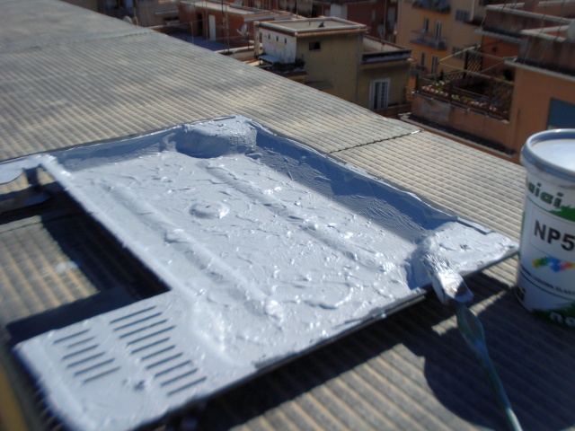 |
| Fig.169, apply outdoors, let dry for a day, then clean out the various holes and ventilation slots |
In addition, we obtain a weight increase of about 400g if spread as in fig.169, a single layer with thickness.
The bottom cover of fig.169 is fixed with only 3 screws, the rear cover of the arm with only 2 screws, it's OK to save money but here it goes too much.
 |
| Fig.170, in yellow the original screw holes, in green the new holes. Above you can still see the original cable before the addition of the RCAs |
The green circles indicate two new holes, threaded with 4 mm parker screws, to fix the bottom cover. The cover must also be drilled. Pay attention to the position of the new holes so that they do not disturb the tonearm rails.
The rear cover of the tonearm shows an even worse situation, it is fixed by only 2 small 3mm MA screws, ready to vibrate with ease.
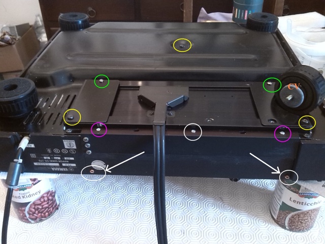 |
| Fig.171, in yellow the original screw holes, in green the new holes on bottom cover, in violet the only 2 screws of rear cover, in white the new screws for rear cover. See the CV=sorbothane disck to dump the orginal feets. To better see the position of the new screws here there is the original photo |
The three screws in the white circle better secure the rear cover of the tonearm. The screw in the centre also has a slot in the arm rail. The other two parker screws with white arrows are very important, they fix the cover to the main frame by reconstructing a mechanical continuity of the main frame.
A turntable platter that rings like a bell if hit with a clapper is a big deal. This is really a difficult problem to solve, with great ease enormous damage is done.
We measure the sound of the turnable's plater
Let's try some audio measurements to know the extent of the problem, let's use some tools that are usually available to an advanced audiophile, such as:
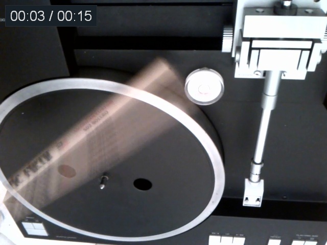 |
| Fig.172, hit the plate, as is, no matt, Video: MPEG4 Video (h264 baseline L1.0, yuv420p, 640x480, 1230 kb/s), Audio: AAC (AAC lc, 48000 Hz, mono, 156 kb/s). The MP4 file is here (3.4 MB) |
The microphone is placed on the left at the same height as the platter, about 0.1m away on a tripod stand.
After a few tries we get "the right hit" and save the recording file.
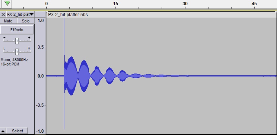 |
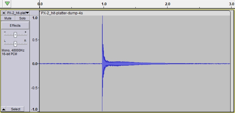
| Fig.173, waveform of the strike on the platter, notice and listen for the shape of the resonance |
Strange platter resonance shape, almost no damping, at least 30s for decay, in contrast a very good balance of the platter evident from the signal shape and sound.
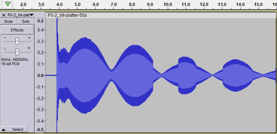 |
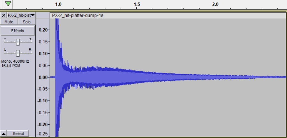
| Fig.174, with a zoom on the first 12s, and on the amplitude, one can see the waveform of the typical sound with beating |
After the first hit you can hardly wait more than a minute to give another hit and hear a "melodious" sound that a bell maker dreams about at night. But maybe that's not good enough for a turntable platter.
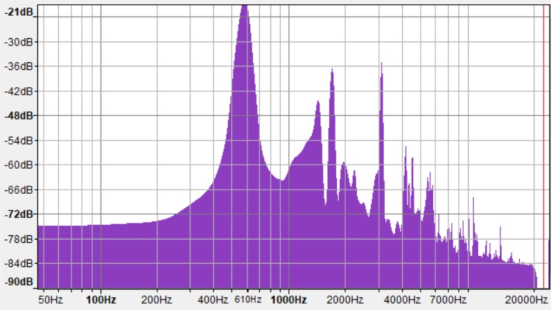 |
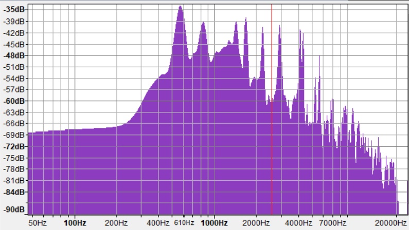
| Fig.175, the spectrum obtained from the sound in Fig. 173 use the window between 0.3724s and 40.412s |
The need for some kind of damping system is obvious. It would be nice to be able to reduce the decibels by half, half, half (-9dB) and reduce the duration to 1/10th.
Some sort of damping
Be careful here, enormous damage can be done. Fortunately, many years of work in the Cultural Heritage field teach us something, a restoration must be recognisable and reversible.
The term reversible is what interests us, even if it will not be an exceptional damping, reversibility allows us to go back and try again.
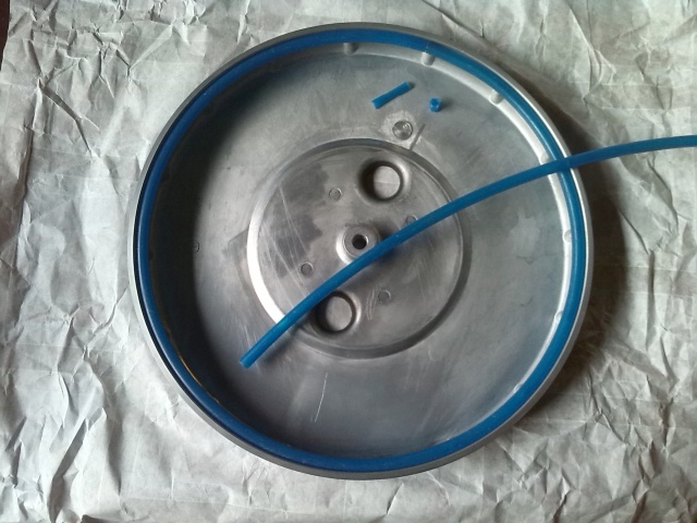 |
| Fig.176, an effective and also reversible damping system |
The plate has a series of reinforcements on the outer edge in the form of studs. The end of the edge is rectified from the inside to a height of 8 mm, slightly reducing the thickness of the aluminium.
It is in this natural recess of the plate that a polyamide hose pipe tube used in the laboratory for transporting high-pressure gases, tens and tens of Kpa, is embedded (as Eaton Synflex 3800 PSI, as Graco BlueMax II 3300 PSI).
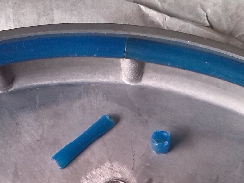 |
| Fig.177, a zoom of the pipe junction point, a piece of pipe, 8mm diameter, can be seen on the right. For the joint, a piece of pipe is cut in half, flattened, rolled and used as a jointing pin |
The pipe is sold in skeins of approximately 0.8m diameter and even when bent tends to return to its original circumference. We take advantage of this elasticity to hold it in place without glue, only interlocking.
From the skein we cut a generous portion for the circumference of the plate. We attempt to fit it into the space available on the edge, it does not fit, better, we shorten it by 5mm and put it back.
By shortening, you reach a length that allows you to fit the pipe without it running away like a spring (if it runs away, shorten it by another 1 or 2 mm).
Figure 177 describes the joining method, with a pin, without glue. The tube must be long enough to stay in place by forcefully inserting it, i.e. not too short.
Audio measurement of the damped plater
We repeat the previous measurements, same microphone, same software, same drumstick, preferably in the same room and at the same time.
 |
| Fig.178, after the intervention in fig.176 we hit the turntable platter several times until we find the right sound to record, note the difference in the time scale |
As in Fig. 174, we zoom in on the initial part of the sound, and also expand the decibel scale.
 |
| Fig.179, the shape of the sound is typical of the object and perhaps should not be altered, but the damping is evident in both duration and beats |
The difference is huge, the duration is much shorter, the shape of the sound reproduces the typical pattern of the object under measurement, but only one or two beats are noticeable.
 |
| Fig.180, the spectrum obtained from the sound in Fig. 178 using a window between 0.95s to 2.789s |
To further highlight the difference between the spectra, we can construct a table with the frequency and amplitude of the main peaks, below.
| Tab.9, measured values for the two platter resonance spectra | |||||
| Platter as is, fig.175 | Platter dumped, fig.180 | difference | |||
| duration (s) | ~40 | duration (s) | ~3 | 37s | |
| 583 Hz | -20.4 dB | 569 Hz | -35.0 dB | 14.6 dB | |
| 826 Hz | -38.8 dB | ||||
| 1430 Hz | -44.2 dB | 1429 Hz | -39.3 dB | -4.9 dB | |
| 1698 Hz | -36.6 dB | 1673 Hz | -37.7 dB | 1.1 dB | |
| 1956 Hz | -59.2 dB | ||||
| 2222 Hz | -61.1 dB | 2208 Hz | -40.6 dB | -20.5 dB | |
| 3106 Hz | -35.0 dB | 2917 Hz | -40.0 dB | 5.0 dB | |
| 4158 Hz | -54.9 dB | 4101 Hz | -39.5 dB | -15.4 dB | |
| 4303 Hz | -42.1 dB | ||||
| 4488 Hz | -55.7 dB | ||||
| 5233 Hz | -53.0 dB | ||||
| 5586 Hz | -61.2 dB | 5586 Hz | -47.5 dB | -13.7 dB | |
| 6968 Hz | -53.2 dB | ||||
| 8593 Hz | -59.3 dB | ||||
| 9491 Hz | -65.9 dB | ||||
| 9728 Hz | -61.3 dB | ||||
| 10897 Hz | -67.4 dB | ||||
| 13170 Hz | -71.8 dB | ||||
 |
PX2-hit-platter-50s.FLAC 2.1 MB |
|
PX2-hit-platter-dump-4s.FLAC 135 KB |
||
 |
PX2-hit-platter-50s.MP3 2.0 MB |
|
PX2-hit-platter-dump-4s.MP3 121 KB |
||
The addition of the tube produces a weight increase of about 35g from which the resonance frequencies should drop by a few Hz.
In fact, the main frequency drops by 14 Hz. The main difference is in the amplitude, which drops by 14 dB. The damping works and well too.
Even more important is the reduction of signal duration. It's not easy to hit the plate with the same force, but we tried. During a real piece of music, the resonances are continuously stressed and having a short decay improves the quality of the audio.
The spectrum after damping is lower in level but richer in harmonics, which in any case are reduced to less than 3 seconds compared to about 40 originally, listen to the two sounds.
The platter mat (Yamaha original, thick rubber) does a great job of trying to dampen the platter itself, but it's not enough. Try hitting the edge of the platter with a piece of wood with and without the mat, you can see a big difference, but now that the plate is damped the mat cancels any attempt of resonance.
And besides, the system is reversible without glue or paint, maybe you can find a tube/pipe that dampens even more.
Before closing the lower cover, now with 5 screws, fig.171, it is much better to repeat the entire calibration procedure as seen on the previous pages, great care should be taken in calibrating the 90 degrees of the arm up and down, reducing the values well below the 50mV mentioned by the service.
Apart from what is written in Yamaha's service manual, what do the services of other turntables that use the same integrated circuits tell us about calibration?
First we need to identify the main ICs in the motor and tonearm control, then look for some other turntables that use them.
For example, a better description of the platter motor and its control can be found on the Victor QL-A75 service manual, read the very useful troubleshooting from page 9 to page 13, which you will NOT find on the Yamaha service manual.
Unfortunately very often we only have a half (1/2) service manual whatever brand we take, see the restoration of Yamaha PX-2 with a lot of lacks and undocumented setting.
A very similar turntable is the Mitsubishi LT-30 although the arm drive is quite different. A similar but different turntable motor unit is the aforementioned JVC-Victor TT-801.
To calculate the monetary value of this Yamaha PX-2 turntable, one should first analyse the condition of each component as described on the restoration page and on this upgrade page.
As you can see, the restoration is complex and few technicians are up to it. Once restored, however, the turntable is of absolute quality. If one even builds an upgrade like the one described here, one reaches levels of quality comparable with objects costing 20000 (twenty thousand) euros and more.
Remember that the sale must include all the accessories of fig.2 and fig.104, otherwise DO NOT buy it.
So how much is this turntable worth after the upgrade?
6000 euro
At least 5000 euros or more with original cardboard box, does that sound like a lot? Try looking up how much the Linn Sondek Lingo-4 or Radikal-2 (Klimax) power supply alone costs :-(
| In the last years at Universita' Degli Studi di Roma La Sapienza |
Dr. G. Visco already contract professor for Chemistry in Environment & Cultural Heritage into --> |
Corso di Laurea in: Scienze Applicate ai Beni Culturali ed alla Diagnostica per la loro Conservazione |