
 |
| Fig.1, our Printed Circuit Board for various Lundahl transformers for Moving Coil cartridge |
Warning! If you are not familiar with electronics, do not attempt to open/repair!
After 2 hours from switch off you can suffer a fatal electrical shock
PRIMA di continuare a leggere queste sono le istruzioni.
please open this one BEFORE start reading
Lundhal is a family business that has passed from generation to generation starting in 1958, Founded by Lars Lundahl and his wife Gunnel in the garage at home (some other industrial history begins in this way) always producing transformers.
Producing transformers, the best, has always been Lundhal's motto but mention must be made of a "magnetic amplifier" without transistors, FETs, Tubes as amplifier mentioned in the US3131360A patent, a project perhaps reborn through a German company.
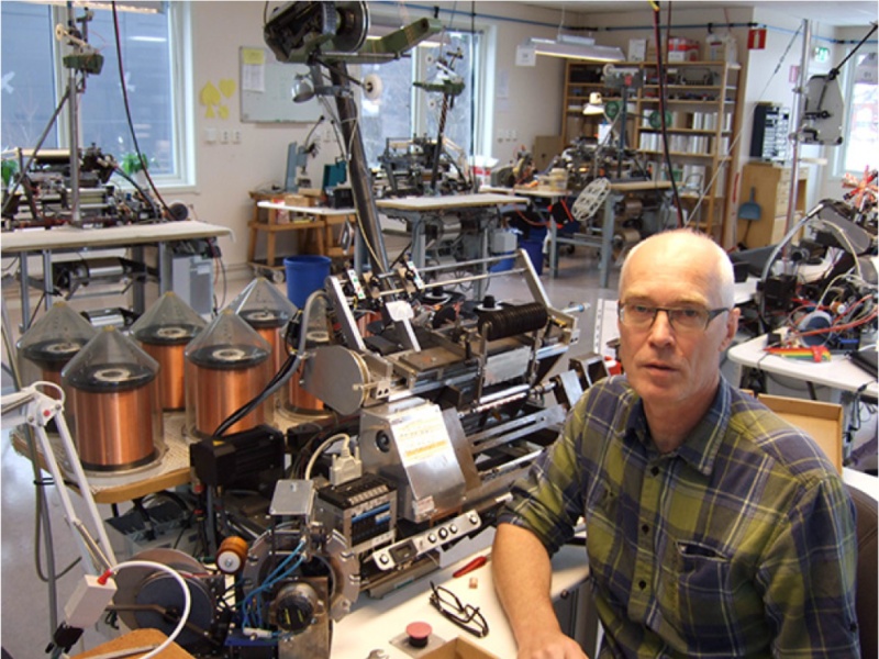 |
| Fig.2, Pet Lundhal at work, see the large number of winders and the chaos-coordinated typical of top hifi brands. |
The history and future of Lundhal is well understood by reading a few interviews:
the use of the PCB is mandatory
The use of a circuit board is necessary so as not to risk damaging expensive transformers. How can they be damaged?
Let's look at some usage examples of Lundhal transformers without PCBs.
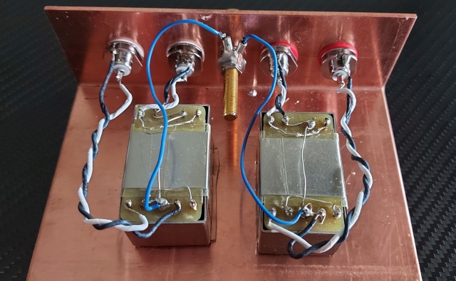 |
| Fig.3, use of LL-1933Ag with Silver coils in copper case but ... see the poor soldering and cable in large image, 973Kb |
A bad test assembly not to be imitated.
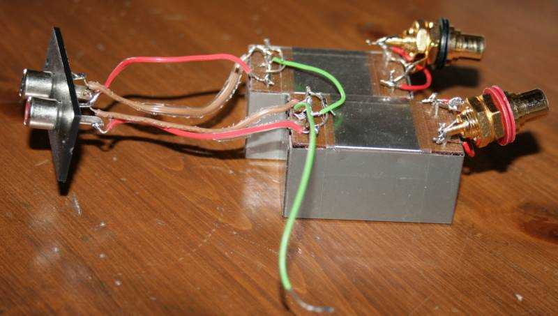 |
| Fig.4, use of LL-1933 in point to point wiring for test, also in this case see the poor soldering and cable |
A little better assembly from small brand company.
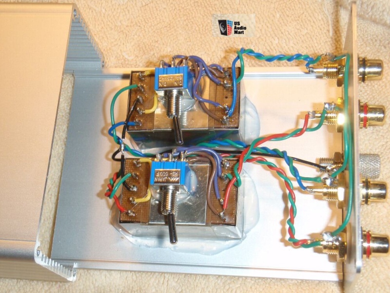 |
| Fig.5, reading an auction on US Audio Mart, from Black Dog using the LL-1933, better soldering and cabling, but not the best |
Here, transformers are used in balanced connection with XLR, an assembly only sufficient.
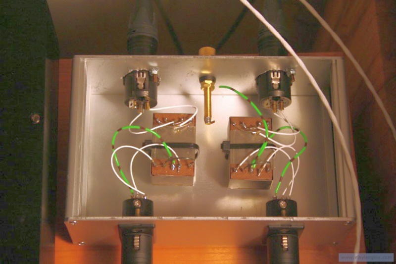 |
| Fig.6, from Vinylengine a discussion on bad wiring for XLRs, good Teflon insulated cables but soldering is the usual disaster |
One of the problems is the soldering on the short transformer pins, it is difficult to solder a wire to them without also melting the internal solder. Also, to do the various tests with the gain you have to solder and unsolder the wires several times.
We have to quote again what Pet Lundhal said in interview (c) 8. How can a transformer be deteriorated and stop working properly? A well-made, well impregnated transformer almost never stops working unless it is damaged physically, most often (as they are most vulnerable) by bending pins or unsoldering the transformer for a new application.
As a final comment on the previous photos, it must be said that soldering a single wire on short pins designed for a PCB is already difficult, but soldering three for series/parallel connections and inputs is impossible without making tin balls and ruining the transformer. This must be said in the defence of the audiophiles mentioned above.
By now it is clear that a PCB is required to mount transformers. In fact, they are built for PCB mounting.
Let us now look at other PCBs already made and/or assembled inside step-ups before describing ours.
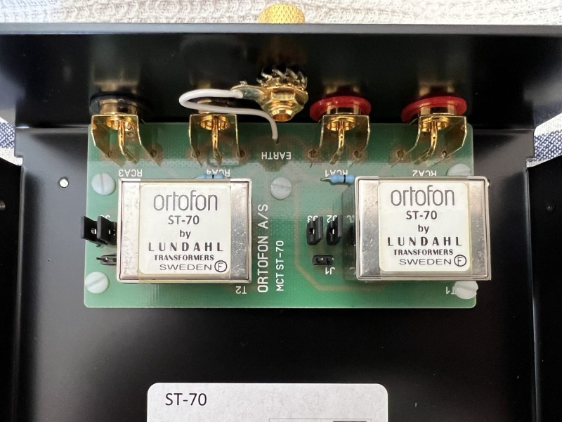 |
| Fig.7, Inside the Ortofon ST-70 step-up there are some Lundhal transformers (which ones?). In the enlarged photo, you can see the circuit board with the gain jumpers, the nylon screws and the toothed washer on the ground screw |
Lundhal fa riferimento ad una prova di uno dei suoi migliori trasformatori, con qualche critica "We agree that the result is a feast for the ears, but probably not for the eyes". See the one in the box below.
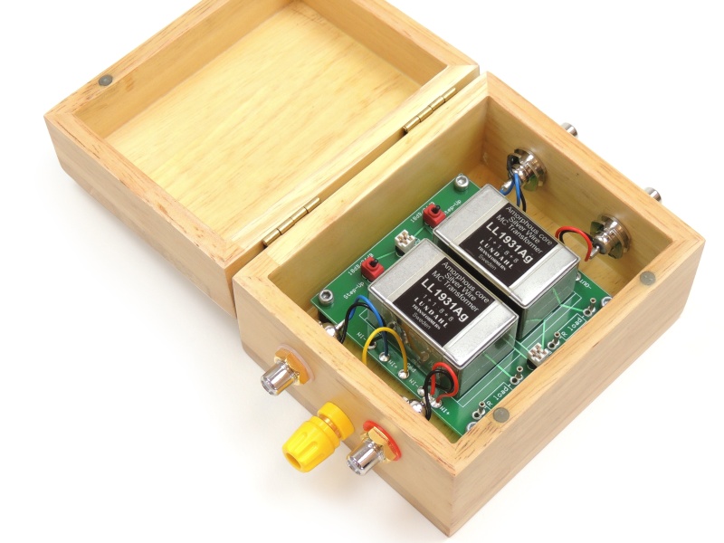 |
| Fig.8, the PCB manufactured probably by Victor Kung. In the enlarged photo of 1.4Mb, note the quality of the soldering, the stainless steel screws on nylon turrets, the RCA jacks, but we also see the wooden case and the non-silver solid core wires |
Many other PCBs are present online with their photos but we do not know how many are really available today, such as the following.
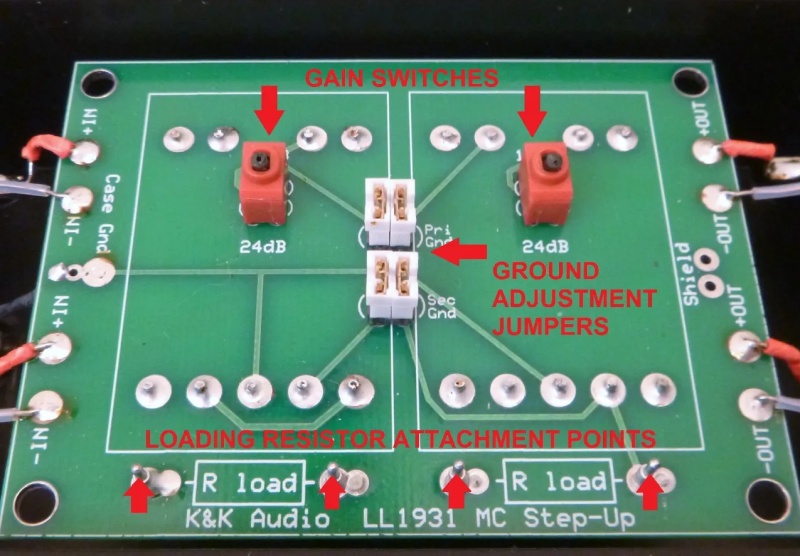 |
| Fig.9, a PCB from K&K audio part of Moving Coil Phono Step-Up Kit |
A project for DIY from Bygselvhifi.dk. On their web pages there is also an interesting earnings calculator for Lundahl step-ups, the mcstepupcalc.zip, unfortunately unchanged from 2012.
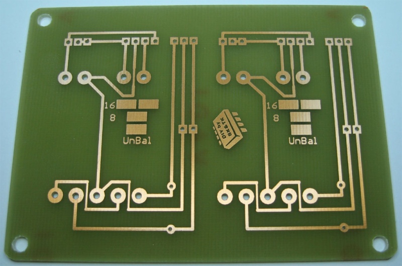 |
| Fig.10, an other PCB from BK&TK for DIY using LL1931 |
A PCB only or some kit with transformers.
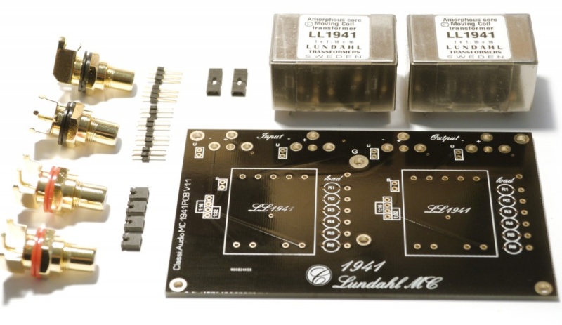 |
| Fig.11, from Don Audio a kit, the PCB seem a copy of Ortofon ST-70 |
Pmillett.com produce a lot of PCB, one also for Lundahl LL9206
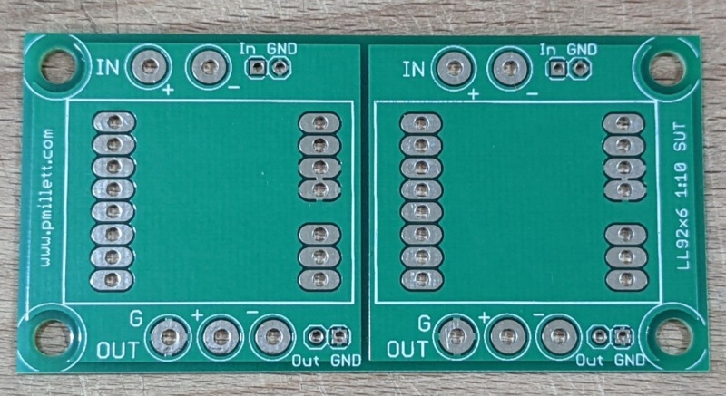 |
| Fig.12, for LL92x6 transformer from Pmillett.com for DIY on Ebay |
Bartola valves in UK is a famous blog and PCB producer for DIY. reading the website we find After a long time, decided to update the PCB of the LL1943 SUT to provide extra flexibility on the grounding connection. This is in essence to ensure no ground loops and noise when either using balanced or un-balanced cabling from the cartridge into the PCB
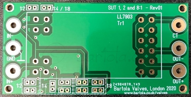 |
| Fig.13, from Bartola valves on of her PCB |
Emissionlabs is probably not the same manufacturer as the magnificent valves that are so popular, but let's look at some PCBs.
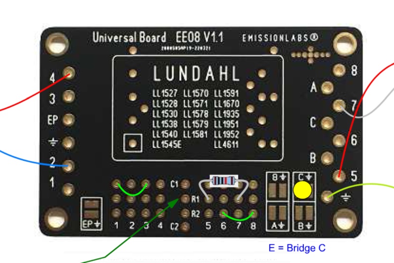 |
| Fig.14, on the JacMusic website a long list of PCB for Lundahl, very interesting description of the problems and possible solutions as Though officially, Lundahl says these are intended for one time soldering only, so be careful with desoldering |
We have certainly forgotten at least 10 other PCB manufacturers for Lundahl MC transformers, we apologise but those shown are already sufficient to show the limits of these designs.
Why is it necessary to have another PCB for Lundahl MC transformers?
First it must be said that there are various pinouts routinely used by Lundhal for their transformers, which depend on the coil-former they use. We see at least three different types in their input transformers.
For our analysis and to construct the new PCB we will refer only to mono transformers, excluding all the excellent stereo series for both microphones and inputs.
We start with the series with the fewest pins, e.g. LL1931 or LL1861 or LL1971 or LL1941 and others with the same mounting pinout space, although with a different layout.
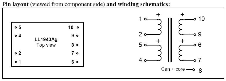 |
| Fig.15, many transformers have this pinout (with core and can on a single pin) |
This pinout only requires a PCB to place the contacts in external pads on which wires or jumpers can then be soldered. Coils can be used in series and parallel, only one coil can be used on the input or output, and the output can be mounted in counter-phase.
Exactly the opposite is another pinout, e.g. LL1545A or LL1544 with four input coils and two output coils. So many many possible combinations.
 |
| Fig.16, various coils, 16 pins, but the interesting part are pins 11 et 14 with the separate shielding for the coils, unfortunately the metal core and the housing are combined in pin 13 alone |
In this case a PCB is, if possible, even more necessary, there are so many combinations that trying to solder wires together is difficult and dangerous.
And lastly, the pinout on which the PCB below was designed. 15 pins used in LL9206, LL9226, LL1678, LL1636 and others.
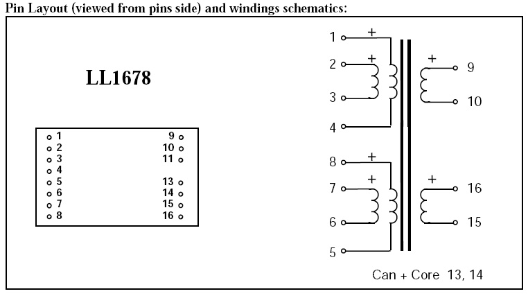 |
| Fig.17, four input coils, 2 output coils, core and box with one connection pin |
Each of the above pinouts needs its own PCB, both for the distance between the pins and for their different connection to the coils.
We must point out an error in the LL1636 datasheet in which the connection pins of the coil screen and core are not understood (see 13, 14 one other 14 and 11 missing).
Which transformers can be mounted on our PCB?
Many transformers have the layout of fig.17 either as microphone transformers, input stage coupling or as step-ups for Moving Coil.
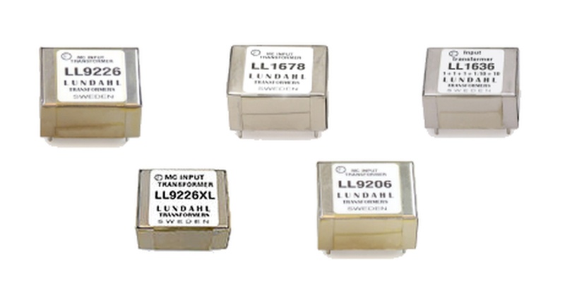 |
| Fig.18, some of the transformers that can be used in the PCB below |
After a thousand words and many photos, we finally see the PCBs produced to mount the transformers in fig.18.
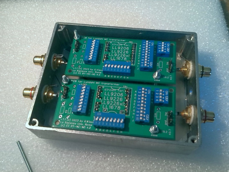 |
| Fig.19, our PCB, mono, fixed in a Mu-metal case with Neutrik Rean NYS-367 RCA. As can be seen, the PCB is designed for an balanced or unbalanced connection from the turntable to the transformers and unbalanced to the preamp. One other may be designed for a balanced connection with XLR |
The assembly shown is temporary, with just two bolts, no wires or soldering, to estimate the available space.
The hum problem and ground paths
With gains of 16 to 30 dB, i.e. with 0.05 mV becoming 1.58 mV to be sent to the phono preamplifier (+30dB) it is very easy to have an unacceptable noise threshold.
Luckily at Lundhal they know the problem and the excellent internal design in fig.16 and fig.17 helps solve it, but .... but ....
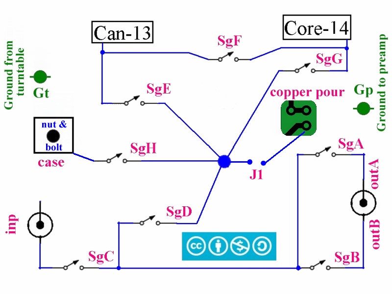 |
| Fig.20, the best possible design for the grounding circuit, many combinations are possible, even with the output in counterphase. Every figure from fig.20 onwards is copyright cc by-nc-nd 4.0 |
Some indications are not there in the drawing: a) the RCA pins are isolated from the enclosure (here called the case), b) the 2 miniature binding posts, for the wires from the turntable and to the preamplifier, are also isolated from the case.
The drawing shows that the transformer core and the box are on two different pins, an excellent choice by Lundahl. Having the drawing in Fig. 20, we can make the first section of the PCB, the ground.
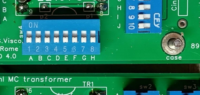 |
| Fig.21, sw4 is a set of dip switches that resembles fig.20, following are the possible settings. Every figure from fig.20 onwards is copyright cc by-nc-nd 4.0 |
In fig. 21 we see the use of Through-Hole DIP Switches (just as an example here is a datasheet) but they must be NO, Normally Open, for the whole description below to be correct.
We note in fig.21, on the right, the large tin-plated pad which, with a nut and rod, is used to connect the PCB to the box containing it (case in fig.20).
The ground design in fig.20 involves a ground-bar to which the various connections lead (the blue dot in the centre), The Ninigi DS-0x dip-switches used are sold in the Normally-Open configuration whereby moving the lever closes the contact. We will now list one by one the dip-switches of fig.20, shown on the PCB of fig.21:
Of the many possible combinations, let us draw one as an example, but one that has its own possible justification.
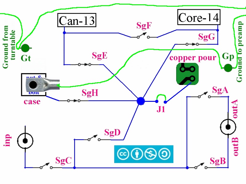 |
| Fig.22, an example, by closing SgE, SgG, SgH and adding a cable lug on the case bolt we obtain the diagram above. Every figure from fig.20 onwards is copyright cc by-nc-nd 4.0 |
Let us give an explanation of the ground circuit example shown in fig.22:
If you want to ground the cables between the cartridge and transformers, you can close SgD and SgC without risking ground loops.
We measure all coils one by one
By choice, we decided NOT to measure all possible capacitances between the 15 pins of the transformer. With ohms and mH alone, we are already bordering on an absolute complication, but it would be good to add µS as well.
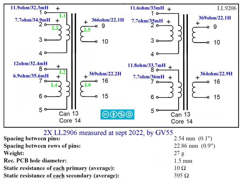 |
| Fig.23, we must quote the datasheet of the LL-9206 from which the original drawing originated, then reworked to include measurements and comments. Every figure from fig.20 onwards is copyright cc by-nc-nd 4.0 |
Having 6 coils inside the transformer we measure them one by one, not out of mistrust of Lundhal but because the datasheet itself speaks of "primary (average)".
Measuring them was fortunate, we find that the four input coils are equal 2 by 2. This opens up immense possibilities for using the primary with perhaps dozens of combinations that, gain aside, would allow for a long list of load resistances/impedances for the cartridge.
| Tab.1, measure on two LL9206 | ||||
| left | right | |||
| ohm | mH | ohm | mH | |
| L1 | 11.9 | 32.3 | 11.6 | 33.0 |
| L2 | 12.0 | 32.4 | 11.8 | 33.7 |
| L3 | 7.7 | 34.9 | 7.7 | 35.0 |
| L4 | 6.9 | 35.6 | 7.7 | 36.0 |
| L5 | 366 | 22.1 | 369 | 22.1 |
| L6 | 369 | 22.2 | 364 | 22.9 |
After measurements, one realises that the pairwise difference of the input coils is intentional, when the output coils are really similar to each other.
All 4 output coils are the same, compliments must be paid to Lundahl for the great consistency of production even on one of the least expensive products (how nice if there wasn't that 6.9).
We are particularly pleased to be able to provide specific connection diagrams (as Fig.20, Fig.22, Fig.23, Fig.24, Fig.26, Fig.27, Fig.29) for many configurations not covered in the Lundahl data sheets, always under copyright cc by-nc-nd 4.0.
Set switch for Output connection
In order to use this circuit board, the audiophile must first understand how the transformer works and then study the possible connections and the position of the switches to achieve the desired connection. There are NO shortcuts if you are looking for the best.
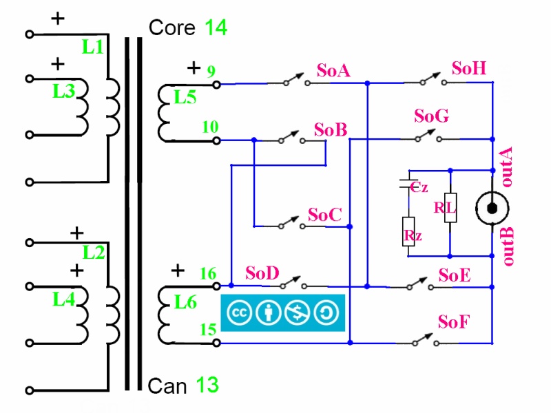 |
| Fig.24, only 2 coils for the transformer secondary, but still a complex circuit including phase inversion. Every figure from fig.20 onwards is copyright cc by-nc-nd 4.0 |
Below is the translation of the drawing in fig.24 into a PCB
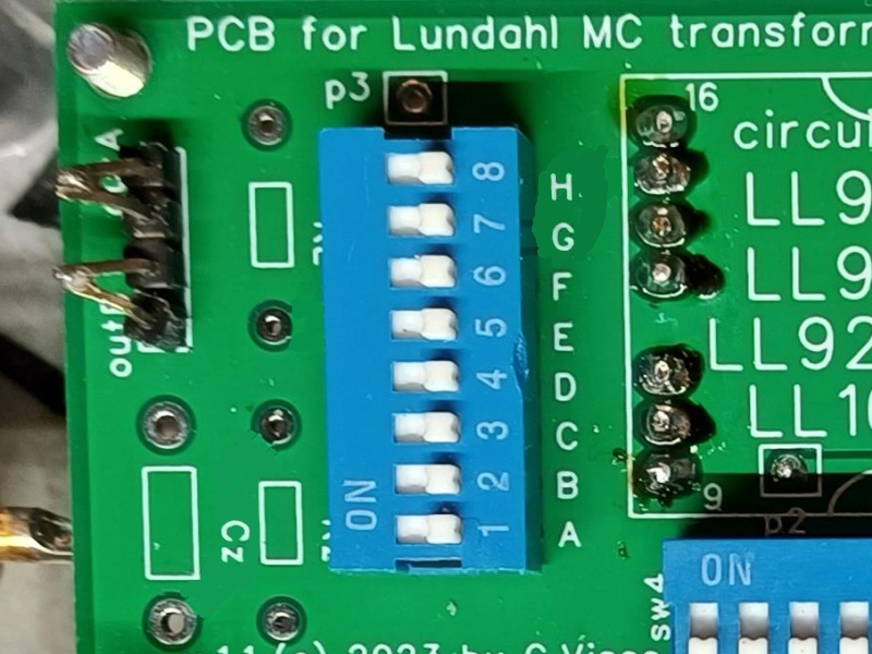 |
| Fig.25, we see on the top left the outA et outB outputs, next to them the place for a possible Rload and on the bottom left the place for Rzobel et Czobel, where required. Every figure from fig.20 onwards is copyright cc by-nc-nd 4.0 |
To connect the input or output pins, doubled and bridged, of the PCB with the RCA jacks let us suggest a few cm of silver wire, solid core, with purity at least 99.99%, diameter 0.8mm. As insulation you can use Teflon tubing or transparent heat shrink (the wires won't touch each other anyway).
Having only 2 coils there are a few possibilities a) connect in series (L5--L6) respecting the phase, b) connect in parallel (L5//L6) always in phase, c) use only coil L5. d) use only coil L6.
Let us analyse the possible combinations, at least the main ones:
Although the output circuit is simpler than the input, one must "understand" it and carefully observe the table above.
Of the many possible combinations, let us draw one as an example, but one that has its own possible justification.
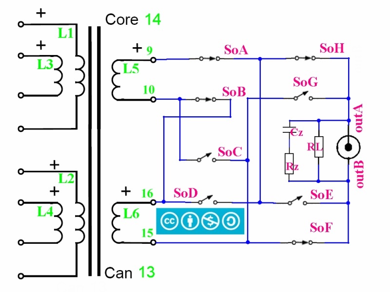 |
| Fig.26, an example, by closing SoB, SoA, SoH, SoF we obtain the 2 coils in series, as L5--L6, and in-phase with RCA jack. Every figure from fig.20 onwards is copyright cc by-nc-nd 4.0 |
Remember that the RCA jack is connected also to SgA and SgB of fig.20 to link, if needed, one of the contacts to ground.
Set switchs for Input connection
In order to use this circuit board, the audiophile must first understand how the transformer works and then study the possible connections and the position of the switches to achieve the desired connection. There are NO shortcuts if you are looking for the best.
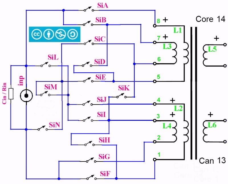 |
| Fig.27, with 4 coils, equal 2 by 2, the possibilities are many and we will try to illustrate them all, including phase inversion. Every figure from fig.20 onwards is copyright cc by-nc-nd 4.0 |
Translating fig.27 into a Printed Circuit is not a simple matter when trying to minimise the space occupied. Below is the result.
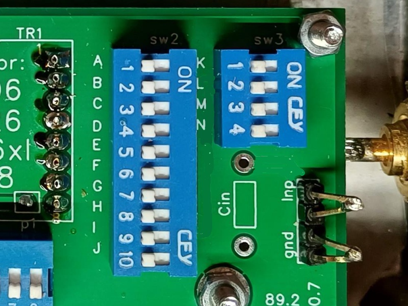 |
| Fig.28, as many as 13 dip switches to cover all the possibilities of fig.26. On the bottom right are the input pins, one for the cable braid and one for the centre, next to it the space for an RFI capacitor (10pF ?), or an Rload for the cartridge. Every figure from fig.20 onwards is copyright cc by-nc-nd 4.0 |
Having four coils there are many possible options for connection. We list just a few ... plausible ones.
But there are many more combinations than 32, and this is not the time to talk about Permutation, Combinaison sans répétition, Arrangement. Let us instead see how to move the switches to obtain 1, 3, 11, etc..
The possibility of using only three coils, and even only two opens up a world of possible input impedances, gain aside.
Remember that the RCA jack is connected also to SgC to link, if needed, one of the contacts to ground.
Of the many input possible combinations, let us draw one as an example, but one that has its own possible justification.
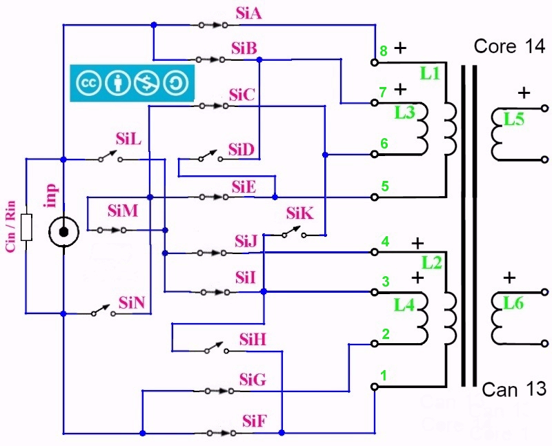 |
| Fig.29, an example by closing SiA, SiB, SiE, SiC, SiM, SiJ, SiI, SiG, SiF we obtain the 2 coils in parallel, in series with other 2 coils in parallel, as (L1//L3)--(L2//L4). Every figure from fig.20 onwards is copyright cc by-nc-nd 4.0 |
Adding up fig.26 with fig.29 we obtain the setting C of the LL1678 datasheet.
Although the circuit is not simple, one must "understand" it and carefully observe the table above befor use it.
How to fit the gains show in datasheet (and measure)
The first thing we have to ask of the new PCB is to allow us to set at least the transformer datasheet gains, perhaps those of the LL1678, which are higher in number.
Remember that this PCB is designed for unbalanced inputs and outputs, with RCA jacks.
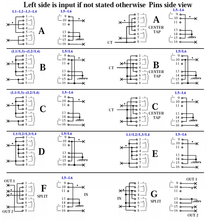 |
| Fig.30, starting with the LL1678 datasheet, we add the coils, and in blue the settings, in order to better illustrate the connections required to achieve the desired gain. See also the enlarged photo. Every figure from fig.20 onwards is copyright cc by-nc-nd 4.0 |
Gain setting C has already been shown, for the others just read the settings in blue and look for the position of the switches in the tables below.
| Tab.2, how to setting one of the gain of Fig.30 | ||
| input | output | |
| A | close: SiA, SiD, SiC, SiM, SiJ, SiH, SiG | close: SoB, SoA, SoH, SoF |
| B | close: SiA, SiB, SiE, SiC, SiM, SiJ, SiI, SiG, SiF | close: SoA, SoD, SoC, SoH, SoF |
| C | close: SiA, SiB, SiE, SiC, SiM, SiJ, SiI, SiG, SiF | close: SoB, SoA, SoH, SoF |
| D | close: SiA, SiB, SiE, SiC, SiI, SiJ, SiG, SiF, SiL, SiN | close: SoA, SoD, SoC, SoH, SoF |
| E | close: SiA, SiB, SiE, SiC, SiI, SiJ, SiG, SiF, SiL, SiN | close: SoB, SoA, SoH, SoF |
Of course, solving the problem of ground and hum, is "your problem" (fig.20, 21, 22).
Let us measure the gain
Given the many possible solutions, series, parallel, mixed, single coil or all, it is necessary to measure the gain obtained.
All we need is a signal generator with low output impedance (preferably 50ohm or less) and a quality AC voltmeter (as only for example, the HP 205A and HP 34401A).
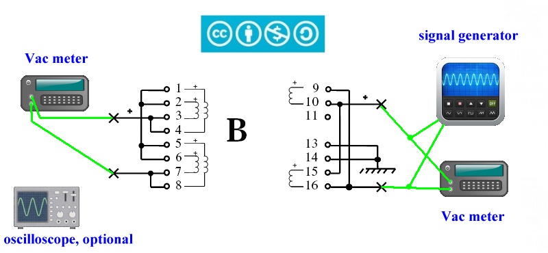 |
| Fig.31, a possible method for measuring gain, explained below. Thanks for the generator and meter drawings to hiclipart. Every figure from fig.20 onwards is copyright cc by-nc-nd 4.0 |
Let's take a step-by-step look at everything needed to measure the gain, in volts, of the transformer after we have chosen a setting by moving the switches.
The biggest concern is not to damage the transformer with high currents and/or voltages.
The author urges you NOT to do this measurement, it is delicate, if by doing it you break the transformer the author of this guide can NOT be responsible for your incompetence.
The author urges you NOT to do this measurement, it is delicate, if by doing it you break the transformer the author of this guide can NOT be responsible for your incompetence.
If you have the appropriate instrumentation and expertise, you can compare your measurements with those of Kurtblum for the LL9226.
Let us measure the resistance
Using an ohmmeter and referring to Fig. 31, one can easily measure the transformer secondary resistance after setting the switches.
Measuring the primary, as already mentioned, requires attention, the expected resistance values are low, even 2 or 3 ohms, and the meter must use a very low current.
As comparison, DO NOT attempt to measure the resistance of a moving coil cartridge without having the right ohm-meter, or using some voltage divider method.
The PCB is constructed as a double layer with ground copper area on the component side, FR-4 material, 1.6 mm thick, TG 150-160, 1 Oz copper, HASL finish with lead to facilitate DIY soldering.
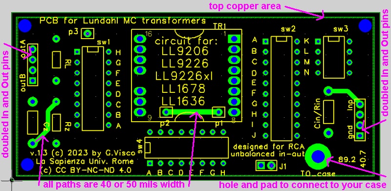 |
| Fig.32, the component side of the PCB, version 1.3, presented in the figures above, as shown by the design software (FreePCB). Every figure from fig.20 onwards is copyright cc by-nc-nd 4.0 |
Fig.32 shows the PCB that is sold now, v1.3, bare, without components, Fig.33 shows the old v1.1 version, both from the soldering and component side, no longer available.
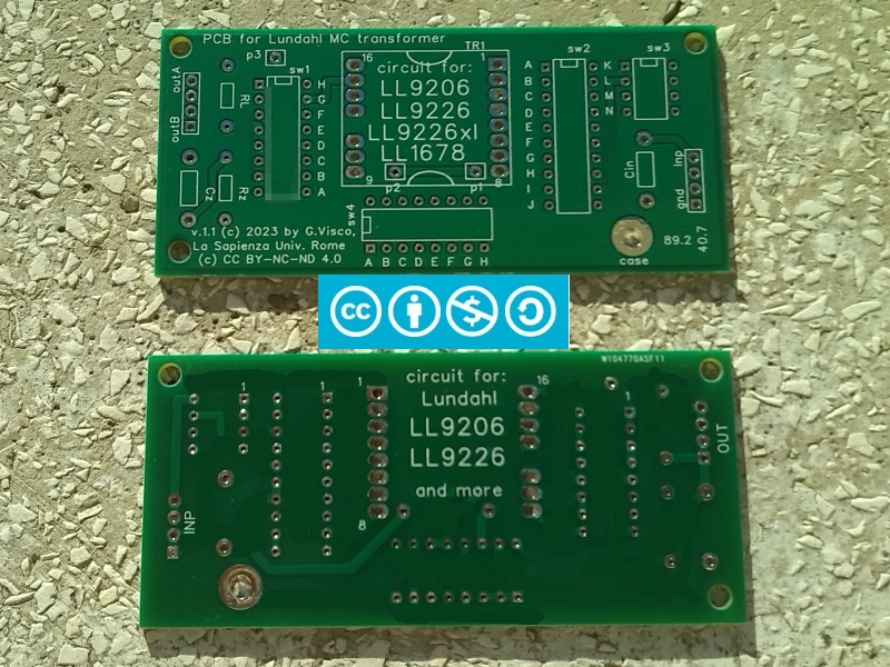 |
| Fig.33, the two sides of the PCB, version 1.1, as they arrive at the trial and test users home. As you can see almost all the traces have been blurred in the photo. Every figure from fig.20 onwards is copyright cc by-nc-nd 4.0 |
Some traces have not been blurred to show the "workmanship" of the PCB where the traces have been widened as much as possible (40 or 50 mils) to reduce the resistance of the paths as opposed to many designs, even emblazoned and expensive ones, which show very thin traces (we do not refeer to Fig.13!).
At the time of writing, July 2024, version 1.3 of the PCB is available as shown in fig. 32 with the enlarged copper area and an improved path design, wider and shorter, in the input section.
Download Geber files
As opposed to many others who try to make money by selling circuits that maybe work (and if they don't, it's your fault) we prefer an Open Source policy.
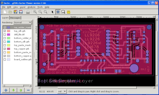 |
| Fig.34, the rendering of Gerber View files from the .ZIP produced by FreeBCB, large view here. Every figure from fig.20 onwards is copyright cc by-nc-nd 4.0 |
From FreePCB manuals "Gerber files - These files are used to create the photoplots that will be used to make the copper layers, silk-screens and masks for the PCB. There is one file for each layer or mask. The format is extended Gerber RS274X."
This is the .ZIP file with all the Gerber files and drilling instructions inside:
Of course the downloaded .ZIP file are under CC BY-NC-ND 4.0 copyright.
A friend participated in the entire development process and mounted two LL9226 transformers on PCB version 1.1 (the old one).
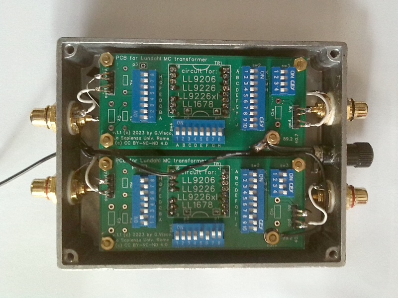 |
| Fig.35, Metal housing, Neutrik Rean NYS-367 RCAs, 99.99% silver wire with 0.8 mm solid core, signal wire as is, ground wire with PTFE insulation, brass bolts and nuts, Sn-Pb-Ag solder alloy. Every figure from fig.20 onwards is copyright cc by-nc-nd 4.0 |
In Fig.35 one of the 2 PCBs has been set for gain E, the other is to be tested, perhaps with D as a comparison. The one in the picture is just an example of an assembly (perhaps with too small case) but well done.
| In the last years at Universita' Degli Studi di Roma La Sapienza |
Dr. G. Visco already contract professor for Chemistry in Environment & Cultural Heritage into --> |
Corso di Laurea in: Scienze Applicate ai Beni Culturali ed alla Diagnostica per la loro Conservazione |