Rome University, La Sapienza
Natural Phy. Mat. Science Faculty
Rome, Italy, Europe |
Dr. Giovanni Visco
Programmi, orari, esercitazioni |
Corso di Laurea in
Scienze Applicate ai Beni Culturali ed alla Diagnostica per la loro Conservazione |
| previous, exerc.12 |
|
exerc. list next |
Laboratory Exercise n.13 (with Arduino)
Threshold level of water by means of its conductivity
(the source, the shield, the scetch, the circuit)
Chemistry Laboratory for Restoration (and Chemometrics), A.A. 2015/16 (by G. Visco)
Maintain the water level
With a pump, of course, but ... . In many laboratory tests is needed to measure when a liquid has reached a certain level and to start or stop an action subsequent.
This time the problem is to keep almost constant the level of distilled water in a Rielem pipette placed against a wall. Conducting automatically all the UNI-EN 16302/2013 Norm is a goal much more complex and difficult to achieve in an exercise. Let's start by maintaining almost constant, at the maximum, the water level in the pipette.
- Rilem who? Réunion Internationale des Laboratoires et Experts des Matériaux, Systçmes de Construction et Ouvrages is a french association that, since 1947, produces recommendations for the study and use of building materials. Just to make us understand the difference with "us" ... stimuler de nouvelles directions de recherches et leurs applications, par la promotion de l'excellence dans la construction...,
- more information on use of the Rilem pipette in this Technical Bullettin (.pdf, 2007),
- a revision of 2015 of the Technical Bullettin cited above, with the drawing of the Pipette and relative wind force, unfortunately in mph,
- on other application of Rilem II.4, the water absorption tube test, from USA, 2006 with some references,
- with some jokes illustration a bullettin, from USA, on interaction of wind, rain, moisture in a wall, with examples of use.
Below, in Figure 1, the issue raised, we note that we will have to use some water level control to understand when it's time to add more distilled water into the pipette with a pump. How to do?.
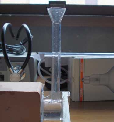 |
Fig.1, the masonry absorb water and the level of
pipette go down, so we must refill and refill
looking for a stability
(but some Norms use a different approach) |
 What we need
This section of the exercises is dedicated to the use of Genuino/Arduino, so we need (with Arduino Uno R3) and some other electronic components.
The idea is that if we put two electrodes in the neck of the pipette, before the funnel, and we measure the conductivity should have a variation in the case of presence or absence of H2O.
Certainly there are 1000 web pages that talk about the conductivity measurement with Arduino but ... since that exercise is for a course of Chemistry some rules must be respected:
- .. about conductivity:
- the electrodes must be of a material which does not interact with the solution. The real conductivity electrodes are on platinum, but it costs too much, some microelectrodes are on gold, but alos are commercially available industrial electrodes in inox steel, we use stainless steel type 316L or 317L,
- the greater the surface of the electrodes is the best measurement in distilled water, but the electrodes must be easy to produce, for example, a dense spiral of steel, 7-8mm diameter, with 0.8mm wire seems sufficient,
- the two electrodes must get well into the pipette neck and must have a distance between them of a few mm,
- the electrodes must be locked in their position, even a small movement would distort the measure,
- you can not use a direct voltage (DC) for the measurement. It serves an AC voltage, many laboratory instruments use a frequency of 1000 Hz try with this value,
- the voltage to the electrodes must be produced and applied so that it is continually reversed the polarity. It's not good a biasing scheme that takes to zero an electrode and various other between 0 and XY volts,
- also the value of the voltage is important, no commercial instrument arriving at 2 or 3 V peak to peak, this is to prevent the discharge, even if temporary, of some ion,
- unfortunately we are having to measure distilled water we expect a high resistivity value (ie, a low conductivity) and given the small surface of the electrodes must go up to the maximum with the applied voltage,
- We do not forget the pump there, that taps a reserve the H2O and ports in the pipette, the pump must stop as soon as a level.
- .. about Arduino:
- goal of the exercise is not to use other chips than Arduino, we will only use diodes, resistors, capacitors, inductors, and wirings,
- generate alternating voltage (AC) with Arduino seems easy, get the polarization of the electrodes is less easy,
- Arduino measure well DC voltages between 0 and 5V but do not measure AC voltages, need a DIY circuit,
- the resolution of the Arduino ADC (analog to digital converter) is 10 bits, maybe not enough, we will see the circuit,
- by everything we need an external board (maybe fixed on the neck of the pipette), veroboard type, stripboard or tripad, with a circuit designed ad hoc,
- and certainly serves a sketch that pilots the above said circuit,
- do not forget the pump, which will have a small flow rate, but certainly you can not be powered directly from Arduino, the sketch will drive an external relay.
If we find some other needs during exercise to add above, now one of the 2 most difficult parts, the drawing of the circuit, the other will certainly the sketch design.
 The circuit
Ask students to draw the circuit during exercise is impossible. Behind this circuit there are many knowledge of electronics and also in chemistry of solutions that perhaps students have not (yet).
But we may ask students to explain it. To justify one by one the components and wiring. But we will not ask to justify brand and models, too difficult.
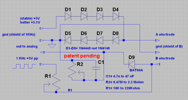 |
Fig.2, the DIY circuit to measure the watere level, by conductivity, in a flash neck, please
use shielded cable as suggested. The A and B electrode, and board, are show in below figure.
LTspice drawing. Be carefull the circuit and design is Copyright Patent pending. |
To a correct view of the circuit above you must have te last version of LTSpice, with sync release from NI web site, and the library of Helmut Sennewald for potentiometer. You can find in this web site the file Potentiometer_by_Helmut-Sennewald_v1.1.ZIP, please expand the .ZIP under - LTspiceIV - directory (this is NOT a course on LTSpice or on their library).
The board
Draw the circuit on white paper, find a provision for components on millimetric graph paper, try to mount them on a stripboard, if they do not collide go to the solder step, is not something that is done in 1/2 hour so the board was prepared previously.
Below the picture of the board (you can do better!), and the electrodes.
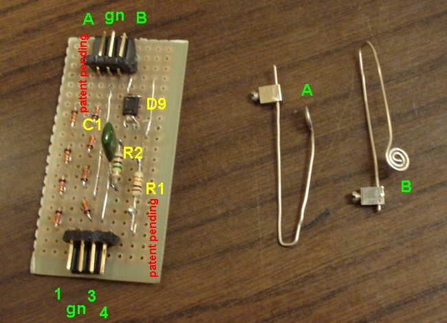 |
Fig.3, the stripboard with components and connectors. The numbers refer to circuit of Fig.2,
as example 4 = 1KHz pin. Be carefull the circuit and design is Copyright Patent pending. |
In the laboratory we have so many old computers case that provide us with both the gold pins that you see in the picture and the wires already terminated (such as those that go from mainborad up to the case's front). To shield we re-use the cable connecting the CD-Rom with sound card.
 L'esercitazione
But if it's all done where is the exercise? Not really, below the task list, then the questions for students must answer.
- .. Things to do before:
- secure the electrodes in the neck of the pipette in a stable manner, connect the wires,
- connect the cables that serve the board,
- connect the wires from 1 to 4 to the Arduino, where? You decide,,
- write down a sketch that produces a square wave at about 1000Hz, 0-5Vpp on pins 4 vs 2,
- try if it works well in the air and in the solution,
- write a sketch that reads the output value from the pin 3 and returns an integer different if the electrodes are in the air or in H2O
- try if it works well in the air and in the solution,
- write a sketch that makes turn the LED on ch13 on or off if an integer is lower/higher than XYX,
- try if it work with some value of XyX, internally generated,
- connect, link, summ the three sketches into one and try if it works in the air and H2O,
- measure the DC voltages and the various waveforms: on pins 4 vs. 2, on B vs. A, B vs. 2, on pin 3 vs 2, always with the A-B electrodes in air or in H2O.
For measurements in DC and for the waveforms, unfortunately, you can not use an oscilloscope (unless it is separated from the mains via a transformer isolator with the ground only on the primary) it is better a hand-scope with battery. Even for %v supply is better a battery system, ie an USB power-bank form Mobile, or a notebook running on battery.
- .. Questions for students:
- what Arduino pins can be connected to the circuit, justify the choice?
- because that strange wire of 8 diodes? Maybe you can not even ask why just "that" diode.
- what is it and why D9? Why has worked so hard to make those welds instead of using a diode as D1?
- how do you choose the value for R1?
- how to pick the R2-C1 values? We can use only C1 or only R2?
- describe the waveform of pin 3 vs 2 in air and H2O, also describe the DC component.
- which is the hypothetical DC voltage that you should have to pin 3 vs 2, with the electrodes in the air? And what you would expect, for DC, with the electrodes in sea water?
- is it sufficient a single reading of the pin 3 by Arduino? If not, how can you avoid this problem?
- after the answer given in point 8, are sufficient the 10-bit Arduino resolution? How can we overcome, in the event of a negative response?
- is better feed continuosly the pump and stop when conductivity raise (electrodes go in water) or measure continuosly the conductivity and feed the pump when the value go down (electrodes go in air)? Be careful the 2 choices has complitely different in the underlined idea of work.
- accounting the reply of query 11, is there a method to solve the problem of ping-pong into the closed loop between pump-conductivity.
 The software
Before moving to programming better study well the waveforms in various conditions and then put on paper the various steps to be performed.
To do this it can be good the reading the wonderful book, (free for the first few chapters) of Ing. Paolo Aliverti. Then, I do not recommend his paper book, expensive and with some bugs, there are another 100 to read, but after!
DO NOT attempt to write all the skecth in one go, before definte on paper the algorithm, then solve only part of the problem (the square wave?), When the running well put away and start with another piece, and so on. It says bottom-up programming and is very useful in microcontroller who always work in the loop. If you can, please, do NOT use library from which little will learn.
The exercise, conducted
qui
Universita' Degli Studi di Roma
La Sapienza |
Dr. G. Visco
appointed professor for chemometrics & .... |
Corso di Laurea in: Scienze Applicate ai Beni Culturali ed alla Diagnostica per la loro Conservazione |
| previous, exerc.12 |
|
exerc. list next |


Back Page
Home Page
C© Copyright
we did it