
|
|
|
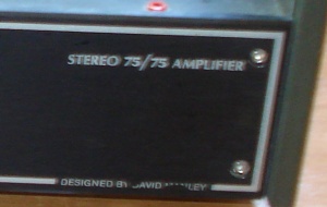
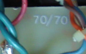
| front, left, the Brand | front, right, the model | but the PCB inside show |
All trademarks mentioned and links are presented here for informational purposes only and to confirm statements made by the author. The author of these pages DOES NOT receive any remuneration from the mentioned brands and the listed links.
In any case if you decide to use the suggestions on this page you do so at your own risk. Repairing electronic equipments, even just opening it, can put your life at risk, so don't do it.
If you do not accept and/or not understand the statements in this disclaimer, written in blue, exit from this page immediately.
Everything exposed in this web page is only a suggestion, probably you won't obtain the aim from you prefixed following it.
Be carefull, a true collector is looking for a) original items without any replaced parts, and with all accessories b) or if a Critical Restoration has been done that it is possible to go back to the original version.
VTL, Stereo 75/75, tube stereo amplifier
David Charles St. John Manley was born in Capetown, South Africa August 26, 1939. Manley first VTL products were originally designed in 1980 in South Africa for recording studios. VTL producing primarily a line of dynamic, extended and fairly priced power amplifiers, the VTL family sound was not 'tubey' or overtly romantic and, in the years, they developed a solid market presence.
Unfortunately (or fortunately depending of you) there are difference between good design, quality schematics and final hardwired products, citing Stereophile: Demand for the products was insatiable, and VTL suffered the typical growing pains. There were a host of interrelated problems: The designs were never fully developed with respect to manufacturability. A lack of resource planning resulted in inconsistent parts availability and quality. The business structure was poorly organized due to a lack of understanding the market. And because VTL was an unknown quantity, it struggled with small dealers who couldn't adequately handle customer concerns, resulting in even more load placed on factory staff. In a nutshell, there were too few people trying to do way too much. At the heart of the matter, though, was the fact that the passion for music and beautiful designs responsible for the products' performance was also responsible for the inattention to the business and manufacturing sides of the equation. The PR-9 Ultimate preamp illustrated the dichotomy. It was filled with tiny circuit boards shoehorned into an impossibly small space and connected with the shortest possible point-to-point wiring. What's more, the boards themselves were packed with vast numbers of components, all of different values and brands. Even the back panel, which would fold down if the wiring had enough slack to permit it, was jammed not only with I/O jacks, but a host of power-supply components as well. It was obviously a "no-holds-barred" design, but, just as obviously, one that was damn near impossible to build.
So the first problem is obtain the "real" schematics, by pencil! The second if study how many different values and brands are used, probably for economy, and design a substitution. Finally check if there is space for some upgrade; a little to not destroy the music quality.
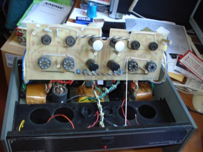
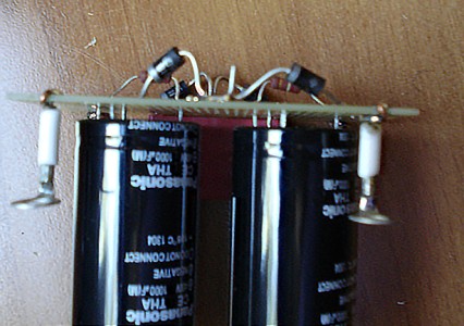
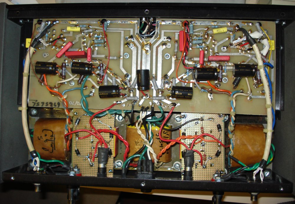
But first look at the photo below, the internal view of this version. There are two bridge on the low right corner of the PCB, strange, but seem original.

(un)fortunately Manley upgrade your products from one model to other and sometime in the versions of the same model, so is necessary the schematics, but ...
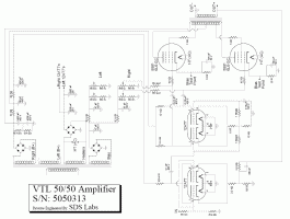
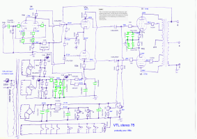
Surely you know the VTL Book, there are some versions available, one are photocopy of 20 pages depliants, other are more the 150 pages, but please read a comment of 1993. Have the small version I find only some approximate circuit but looking for in Internet I find the schematics below on the left, no other. Butt the book is also on Goggle Book.
 |
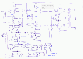 |
| VTL 50/50 from internet, circuit | VTL stereo75, schema by pencil |
| This circuit has been obtained by following, and drawing with pencil, all the tracks of the amplifier. 2013 GV55 | The scheme can be used for the purpose of study and research or for teaching in an electronics laboratory |
Having schematics, the restoration
Before proceeding you must be careful; ANY change to historic and vintage HiFi will reset the value for "a collector" who seek/need only original goods in its entirety parts. If you need to repair equipment like this one you should use original parts (with great effort and expense to find it), almost like a historical car.
The broken parts are the main capacitors (2 are removed, on the left, on the above photo). So we must speak for long time with the owner. Discuss on parts to be replaced, look along the broken components and possible replacements, do some drawing of how the object is after restoration, discuss the market value before and after, (this almost never happens with "a service", only between friends).
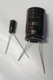
Discuss is useful, we select all Panasonic capacitors for power supply, and all Silmic II for others (Bias and Cathodes). Only two brands, and only because not exist Silmic with 450V.
Panasonic 400 and 450V are easy to obtain, so waiting for the Silmic II we mount Nichicon Muse KZ capacitors. After almost 100 hours of break-in we can mount the Silmic II and listen/search to the differences!
 |
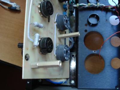 |
| the other side of the PCB, see the 3 small bridges on centre | someone have add 10 mm to spacer |
Above the other side of the PCB, and more space on the tower to fix the PCB itself. Strange, all components are on the wrong side of the PCB. Normally resistors, diodes, capacitors, sockets and links are on the component side and none in the solder side (in better tube amp/preamp capacitors are in the "other" side of tubes to remain cool).
The idea is use top quality components but inexpensive. Some words on the use of "same" values: as example on the cathodes there are 100µF/50V and on the bias supply 47µF/100V, in my opinion use a low number of components is better, a tube amp/pre is not a Greek salad, so we buy only the 100µF/100V and use in all positions.
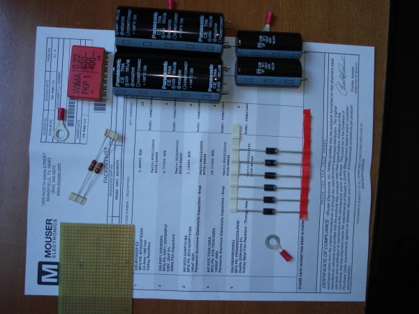 |
| the components used for repair high-voltage broken section |
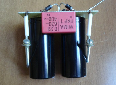
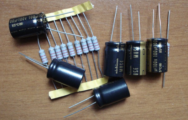
As already said the main problem was the high voltage capacitors. So we buy: 4x Panasonic CE THA 1000µF/400V, 105°C, 4x Panasonic CE UP 150µF/450V, 85°C, 8x BY255, 2x Wima FKP 0.22µF/630V, 4x Vishay 200Kohm/2W, a multiholes PCB board with 1mm copper wire for fixing. Above the receipt with the components.
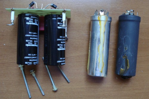 |
| on the right the old capacitors, on the left the new circuit |
Why a new board?
 |
 |
| the new board, see the space under capacitors and short link | the other side, the screw removed from transformer |
Be careful when you remove the screw, make only in one side and make attention to not unscrew the turret used to fix the transformers. If the turret become slack is very difficult to repair.
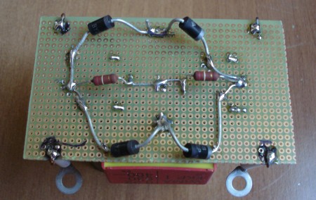 |
| the components side, no wire, only the rheophores of diodes and resistors |
One other problem. The output socket are nearby the new board. In the upper right corner of the board you can see the diode bended to avoid contact.
Waiting the Elna we like to make a tentative with same quality (or better?) capacitor, Nichicon Muse KZ, as in the photo below. See in the mod. schematic, we like to use "same values" and "same type" policy, if possible.
 |
| capacitors for π bias supply, and for cathodes |
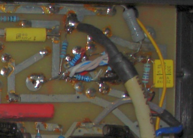
And finally the VTL is ready for test, see below. On the bottom right corner you can see a green cable, insulated, useful to obtain the 4 ohm output (but probably is 5 or 6 ohm). In the right upper corner the modification on the first tube, the two 1Kohm grid stop, the two 44Kohm for cathodes, separate. 2 of the Wima is burned when soldering in one the previous repair, work but is better a replacement.
 |
| all new components are installed but for obtain space the already show 1cm spacer was removed, and the modification on the right channel |
Obtain ELNA Silmic II is not so easy. There are a big number of sellers but having only 10 or 50 values in place of more then 500 in the catalogue (also there are some fake capacitors). Waiting, original, below the suggested schematics with modification.
|
 |
| VTL stereo75, schema by pencil | modified suggested at stereo75, schematics-mod |
| This circuit has been obtained by following, and drawing with pencil, all the tracks of the amplifier. 2013 GV55 | The scheme can be used for the purpose of study and research or for teaching in an electronics laboratory |
Arrived the Silmic II the VTL was desolderd and the new capacitor was fixed, also I must find a solution for the little, but evident, noise.
 |
 |
 |
| 100uF and 0.47uF | parallel, insulate, mounting | the input wire, white/blue, and the resistors |
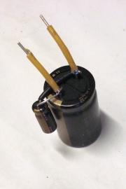
Having a very good capacitor for bypass cathode (cut away the small local feedback), as example Silmic II, 100uF, 100V, what capacitor we must use to bypass itself?
You can reply with an unbranded 0.1uF/100V polycarbonate, up to 1uF Duelund CAST expensive as half of the amplifier. After you can discuss about speed, slew rate, frequency response, two way filter similar to a speaker, ESR, and continue for months!
My reply is simple, and sound well, same brand, same model, same type, same voltage, different capacity, about capacity to bypass is better use values from 1/1000 up to 1/100 of original, in this case I select 0.47uF/100V as show in above left photo.
Noise: on the above right photo we can see the white/blue input wires, coming from pin-jack, soldered to 100K and two 1K resistors. In previous modify all are in-air, the wires and R bend and vibrate, probably this is the input of small noise. Having an empty pad near I make a bridge as in photo and solder to, it is more stable, hoping the measures confirm.
 |
| With the new capacitors, see parallels, with the input wires fixed, a Wima show melting produced by previous soldering, changed |
Those are not a measure set. Only some values to check if amplifier works well. For all of the following measures I show the poor channel, the other is little better. First start with overload, only 1 dB can show really the quality of power amp. See the correct of symmetry circuit, not so easy to find without pot for setting (as in Marantz 9, an example of legend).
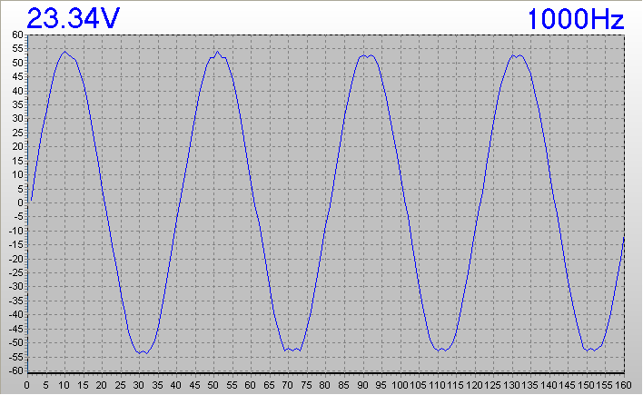 |
| VTL stereo 75, 68W at clipping, 1KHz signal, 8ohm load, only 220V supply (in place of 227 stated) |
I apologize for the enemy scale but all graphs where obtained using Uni-Trend 81b scopemeter. The instrument is interesting but the software is criminal, see comments below.
Next graphs: the noise from the poor channel, see the values and signal form.
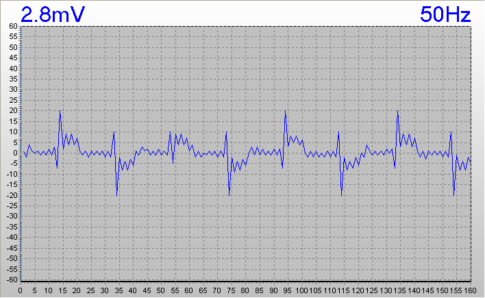 |
| VTL stereo 75, noise, the input pinjack is open to obtain the real noise (my opinion) |
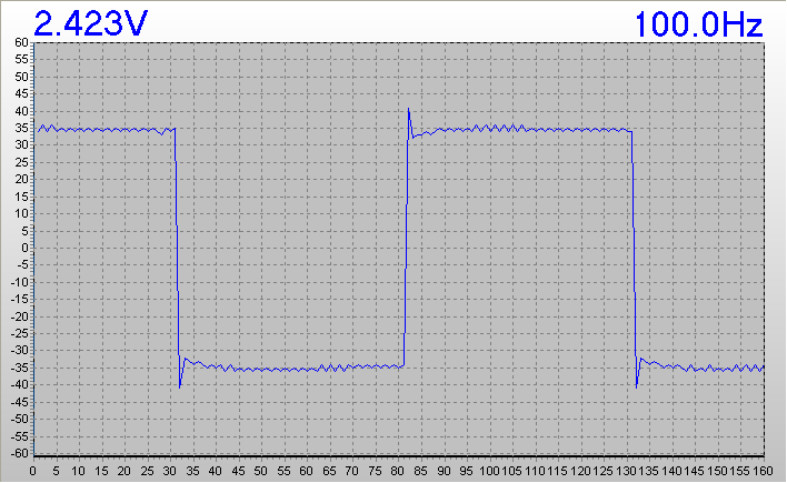
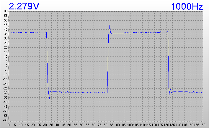
Next a sequence of square signal, from 100Hz to 10KHz in 8ohm load.
 |
 |
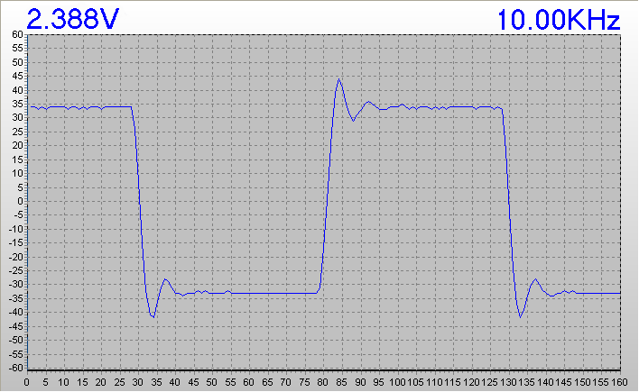 |
| VTL stereo 75, output at about 1W/8ohm by square signals |
The signal is good, with some overshoot, but I must check more the "load", probably there are some capacitive or inductive components. Next work.
To check better the problem of ringing I use a single resistor Dale 8.2ohm/50W metal case in those measures.
Incredible the version 3.01 of UNI-T criminal-software show the voltage value, hurrah!! (but in the LCD of meter we can read: voltage, frequency, time division, and Y scale, probably is too difficult to transfer to PC). The software in a laboratory-instrument is "half" of the instrument, a magnificent hardware without good software is unuseful.
Next graphs: the noise from the poor channel, see the values and signal form.
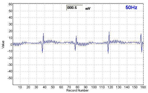 |
| After modify of input wires the figure noise is lower and better |
Next a sequence of square signal, from 100Hz to 10KHz in 8ohm load.
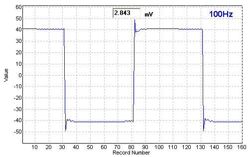 |
| Better but some problem in the straight line of square remain |
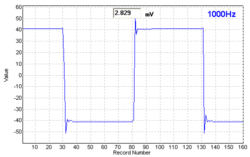 |
| Only 2 ringing before the straight line, better |
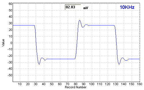 |
| On 10KHz we see more control with only 2 overshoot, better |
The difference probably is not produced by the Silmic II itself. Probably one difference is in the bypass small, 0.47uF, shown in the 10KHz. One other difference is due by the load, only a large resistor mounted directly to the banana socket.
The owner is a famous italian Audiophyle, build itself speakers, buy and sold speakers and HiFi equipments. I really do not konw how many Hifi have under the hands in previous years, more and more.
One of the most "onest sound" according to him is this VTL, so I ask him to write down some considerations on the different sound of this 2 brands, following:
My VTL stereo 75/75 following the installation of II Silmic capacitors Elna capacitors, compared to Nikikon Muse KZ, is significantly improved in the tonal profile and noise; there are no significant changes in its general sound, as the extremes have increased bandwidth and also the speed. In this it has also affected the small bypass 0.47 microfarads capacitors.
It's a powerful amplifier, quiet, with a slightly dark timbre. It is sensitive to power cables, so you may want to provide it with an adequate power line cable.
This scopemeter is probably not one of the more inexpensive (or one of the cheapest). After 3 months of use, in comparison of HP, Agilent, Hameg, Beckman my opinion is:
PRO
CONT
Donations if you have a Bitcoin wallet
If you have a nice fat wallet you can send a few cents to this code 1ETv1mJTZTB7EiXwZkucF2BTA512Rkaw6 maybe with a message (be careful to the transaction cost, send 0.1 and pay 0.01 is not a good idea).
1ETv1mJTZTB7EiXwZkucF2BTA512Rkaw6 <== my code , Thank you.
Donations if you have not a Bitcoin wallet
If you like this work and measures you can make a small donation of Bitcoin. You do not need a wallet to make a donation, indeed even those who have Bitcoin wallet is better to pass for a web site that "gift" currency since this does not have a transaction cost.
To make a donation you must use some of your web-time on a Bitcoin Faucet, please go to Kickasstraffic.com, enter my code 1ETv1mJTZTB7EiXwZkucF2BTA512Rkaw6 into empty cell and press "Start Earning", a new sub-page appear, do not touch other then the last 2 buttons in lower right corner "Surf Ads" and "Active Window Ads".
If appear a tweet asking to register use the lower right corner button "Close", solve the Captcha and proceed. Of course any next page if different but I suggest you to stay more time possible reading pages and advertisement to produce Bitcoin (1/100000 I suppose) for me.
Be careful, do not use roulette, dices, casino and other stealing web site, as claim of supposed infection. We use Kaspersky Free Antivirus by 2 years without problems.
1ETv1mJTZTB7EiXwZkucF2BTA512Rkaw6 <== my code , Thank you.
| In the last years at Universita' Degli Studi di Roma La Sapienza |
Dr. G. Visco already contract professor for Chemistry in Environment & Cultural Heritage into --> |
Corso di Laurea in: Scienze Applicate ai Beni Culturali ed alla Diagnostica per la loro Conservazione |