|
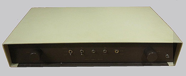
| Croft Super Micro, in brown/cream version, 2 volume pot. |
Warning! If you are not familiar with electronics, do not attempt to open/repair!
After 2 hours from switch off you can suffer a fatal electrical shock
PRIMA di continuare a leggere queste sono le istruzioni.
please open this one BEFORE start reading
All trademarks mentioned and links are presented here for informational purposes only and to confirm statements made by the author. The author of these pages DOES NOT receive any remuneration from the mentioned brands and the listed links.
In any case if you decide to use the suggestions on this page you do so at your own risk. Repairing electronic equipments, even just opening it, can put your life at risk, so don't do it.
If you do not accept and/or not understand the statements in this disclaimer, written in blue, exit this page immediately.
Everything exposed in this web page is only a suggestion, probably you won't obtain the aim from you prefixed following it.
What you see in the picture is a Croft Supermicro, Limited Edition, serial number 556, of a friend who bought it used and modified already.
The job was to weed out the change, reconstruct the original scheme, check if any component was worn by time, and do some updating.
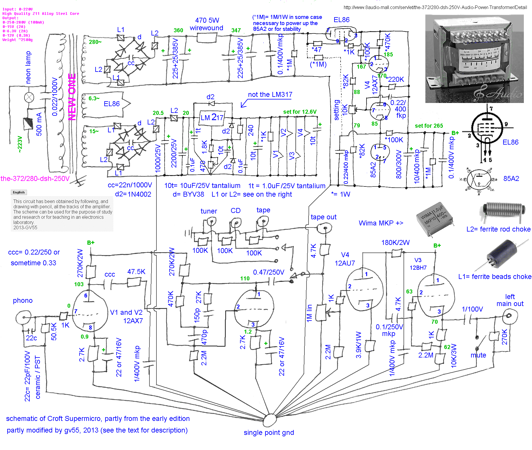
It was not possible to find the original electrical diagram/schematics. But looking carefully all the components it was possible to obtain the wiring diagram of this pre (no one ensures that all Supermicro have this schematics). Exchanging a few messages with other audiophile and fans I got a schematic that does not seem, to me, of the Supermicro (3 valves per channel!?). However to those who can serve here it is.
On the recommendation of a friend of mine instead, I found an english page with layout and description, really nice, but it is a later model, thanks anyway.
Years and years after the construction of this page an other audiophile work on a different Supermicro and confirm the schematics with a few differences, already in the presented schematic.
Be Careful: the schematic diagram is referring to this pre only. None can certify the same circuit for other Croft Supermicro. Often the producer make little variations, serial number by serial number, increasing.
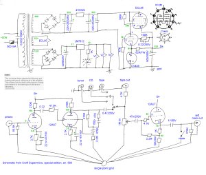 |
| circuito elettrico, schema elettrico, componentistica (186 KBytes) circuit diagram, schematic diagram, wire map, components map (186 KBytes) |
The following is the picture of the sample I used to get the wiring diagram, voltage and components values.
 |
| Croft Supermicro, lo schema elettrico viene da questo, the schematic diagram came from this preamp |
Eradicated the change (I suspect to increase gain) you can switch to some small, non-invasive updates with some simple interventions.
This preamp is interesting for the passive RIAA between the 2 triodes, so with some little upgrades you can obtain a high quality audio preamp able to compete with 10x price equipment. I think there are at least 2 chances to upgrade to this good preamp
we try to list the 2 hypotheses which are consequential
In this step we obtain: a better filtering of High Voltage (HT) using some small caps; the increasing of the section of the wires that carry the voltage from the filter capacitor to the valves; a better balance between left-right stages, taking into account the economic potentiometer used for the volume; an improve of the filaments circuits to obtain a more stable supply; return of some resistors lacking, but necessary as stated by old RCA, GE, Siemens data sheet.
 |
| modifica1 al circuito, schema elettrico, in viola (187 KBytes) modification1 to circuit, schematic diagram, purple components (187 KBytes) |
Starting ....., please see the previous photo, see the main transformer, it is a good idea to change the metal nuts and bolts with other, of the largest possible section, nylon type, also using nylon washers on the head and the nut, better interpose between the tabs of the transformer and the chassis plate a wide rubber (from the air tube of a bicycle?) to decouple the whole, attention to the final height, the transformer must NOT touch the lid otherwise it is almost worse
Locate the large capacitor (silver, at the top right of above photo). Its function is to filter the anode voltage after the stabilizer. Allow me to recommend the addition of a capacitor, in parallel, 10uF/400V and also a bypass capacitor 0.1uF/400 (the yellow one visible). The capacitor 0.1 has to be soldered in parallel to the axial 10 uF. Now the capacitor of 10uF must be glued on the bottom side, and the leads, insulated, soldered in parallel to the filter capacitor of 800 microfarad. I suggest the red Wima FKP, good and inexpensive.
We must also double the main wires. Use wires of the same diameter and insulation. One green must go from the - of capacitor(s) to the single-point-ground (sorry, black in the figure) and the other, red, from the capacitor + to the anodes of the ECL85 (sorry, orange in the figure).
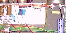 |
| croft supermicro la prima piccola modifica, the first small upgrade |
Now we would have to work not just on the stabilization of the filaments. Remove the nut and bolt, add a small lug under the nut remounting, so we have links to add two 0.1 uF/100V directly between rheophores of 7812, then add a capacitor 47uF/25 V between its output and ground (the new lug). Parallel with new capacitor add resistor 1Kohm/0.5W. Please follow the filaments wires tube by tube and add another 47uF/25V in parallel to the last filament of the chain.
Use the 1Kohm of the LED for minimum load for 7812. Remove the led and substitute with a 230V neon lamp connected after the main switch. Be careful with wires, first for the use of main voltage, second for noise injected on the preamp by poor flying wires.
Some resistors, capacitors, diodes missing: see the schematics for phono grid stop and radio frequency cut, or all the new diodes, as example. All additions are electrically easy to understand, but mechanically complex as seen the small spaces.
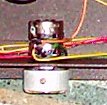 |
| croft supermicro la modifica ai potenziometri the upgrade on the gain pots |
Another problem are the potentiometers that must be from 1.0 Mohm (1000 Kohm) since the output stage, see circuit. But it is difficult to find two alike. Luckily much Croft equipment use two stereo potentiometer, one for each side. Thus there are 4 possibilities!
Calling front the 1/2 potentiometer closest to the metal panel and rear the other inside, you can try reversing the connection of potentiometers. The alternatives for connections are:
Once you have chosen one of the four above possibility must be checked by a signal generator and a precision voltmeter the gain as a function of all positions of the knob. Then you change the wiring arrangement and try again. So it is possible to write down a multiplication table with all values position-knob vs volts-output. Please use a small signal from 1 to 2V, similar of the real use of the potentiometer but avoiding noise.
For this test I disconnected both potentiometers. With a precision generator set to 1000 Hz, 2.5V I fed the input potentiometers and then measured the two outputs simultaneously with a digital two-channel scope-meter.
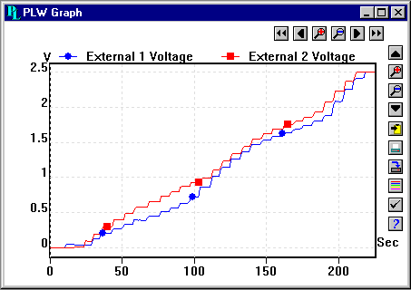 1) left rear, right rear |
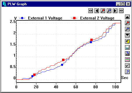 2) left front, right rear |
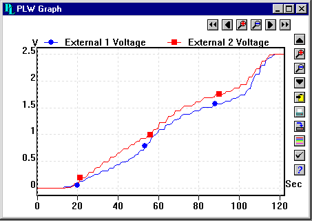 3) left rear, right front |
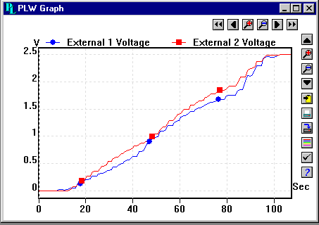 4) left front, left front |
Above the four curves obtained. The position seems to be the best is n. 2, and so were soldered potentiometers.
Last step is the balance of the phono gain, the only method is to reverse the two phono's valves. For the balance the line gain you can only replace the line's valve. Attention, the preamp is very sensitive to the quality of the mounted tubes.
The small upgrade end here, next a construction of a new, modern preamp using ideas and circuit of Glenn Croft!
In this step we work only on "supply", by change the transformer, the HT power circuit, the filament circuit and so on. Of course all modify on the phono/line remains.
the new transformerOne other Audiophile (Vincenzo) discuss with me about the supply of Supermicro and check if it is possible add a 12AT7, or similar, after potentiometer to obtain gain. There are in the world of circuits almost 1000 schematics for this! We can present the voltage after and before the addition in the table below.
| position | V before | V after | ratio % | note |
| transf. HT~ | ~298 | ~285 | 95.6 | transformer overloaded, but we must check the V form with scope |
| before 470ohm | +368 | +347 | 94.3 | the ~/+ ratio=1.22 not a typical 1.38, but seem ok |
| after 470ohm | +359 | +334 | 93.0 | from 19 to 28 mA, probably a choke is needed |
| ECL85, p1 | +260 | +263 | 101.2 | ok, the circuit modify the internal values to maintain B+ |
| main B+ | +268.0 | +267.4 | 99.8 | the stabilisation of HT work well |
| transf. LT~ | ~14.97 | ~13.8 | 92.2 | the transformer is heavy overloaded, check the V shape |
| 7812, p1 | +16.4 | +14.7 | 89.6 | the diodes also are overloaded (~/+ ratio=1.07 not 1.41!) |
| 7812, p3 | +12.0 | +12.0 | 100 | incredible the 7812 work under drop-out specification |
The suggested circuit come from an old equipment using an EL86 and 12AX7 in place of ECL85, the supplied transformer are really big and mounted in horizontal to fit the case. Find one other in Internet is easy, but difficult if you need quality, I find one in the well know 8 Audio brand (famous to clone some old amp), please see Audio Power Transformer (I/WE HAVE NOT CONNNECTION WITH THIS BRAND, IT IS ONLY AN EXAMPLE, NOT SUGGESTION).
having the transformerI find this photo, one years ago, in internet of the early edition, but heavy modified in the power supply, from right you can see the 2x 12AX7, the 12BH7, the EL86, the 12AX7, and hidden the 85A2.
.jpg) |
| the dsc01028u.jpg photo of the old edition, from internet but the EL86 and 12BH7 need some form of fixing or fall after some months! |
The upgrade is:
The new rectifiers diodes are the BYV37 or the BYX10G, fast recovery type. But those diodes can produce some spikes to be filtered by small chokes after and before diodes, with different values.
In the 2 new bridges there is a snubber capacitor soldered on the diodes leads. Also the chokes are soldered on the leads.
The diodes on the new LM217 remain 1N4004, slow and useful in those positions.
new, variable, HT stabilised power supply
The old stabilisation circuit for High Tension use 3 tubes, the 85A2 equivalent of a modern zener (but probably better for sound), the 12AX7 to pilot the grid of the power tube, and the EL86 as power tube. In a lot of Supermicro models there is a noval socket free (or a hole) to mount the 12AX7.
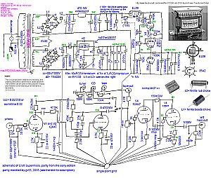 |
| Croft Supermicro suggested modify n.2 nuovo circuito, schema elettrico, (276 KBytes) new circuit, schematic diagram, (276 KBytes) |
So it also recover the possibility of varying the B + voltage between about 250 and 280V with a cermet trimmer. The output stage was equipped with a magnificent 12BH7 supported by the new larger main transformer. The 11K for cathode is too low for the 12AU7 but good for the 12BH7, for years of working.
Compare the figure above with the original schematics. Some parts are completely new, other original.
LM217, not 317, for filamentsAfter the new rectifiers diodes is better use a pigreek filter, see figure, with a best sound method of climbing values for capacitors. In this manner we obtain a circuit with variable setting from 10 to 13V and you can check, by self, the famous difference among filaments voltage!
In place of 7812 standard I suggest the LM217, variable, linear, up to 2A, with a good sound. Someone suggest the new Low Drop Out type as stabilizer but those are practically a switching, not really good for sound. Also the LDO are not necessary, we need some "fall" of voltage in the pigreek and a transformer of opportune voltage and with a good design use the LDO is useless.
Please see the capacitors at start and end of the filaments paths, it enhances a little the sound.
The LM317 is the standard chip, but LM217 (not so easy to find) is the high quality version, more stable with temperature, use it.
output stageMore and more preamplifier uses two tubes for the line stage. Reading RCA, GE, Siemens, Mullard old data sheet surely we can find a schematic "securely working" so the circuit for new 12AU7 is a copy of an old data sheet. The new values are 180K/2W for anode and 6.8K/1W for cathode, a few current for years and years of working.
All the preamplifier suffers of the problem of "ground loop", a possible loop between earth (necessary for safety) and ground of power supply, through the pin-jacks, or through the tonearm shield, or ... . There are a lot of discussions on the use of pin1 of XLR also.
.gif) |
| avoiding heart ground loop, a solution from GV55. the cap is Wima MKP |
This is "my solution" starting for some schematic of Nelson Pass, from the modification of Rod Elliot, and finally with some addition by me. The sonically-selection of the capacitor values is yours, please check also with the addition of 1nF/630V ceramics in parallel to resistor.
The square box of diodes can be fitted with 2, 4 and 5 diodes to obtain a different values of "insulation" between Earth and Ground to cut the ground loop, see below.
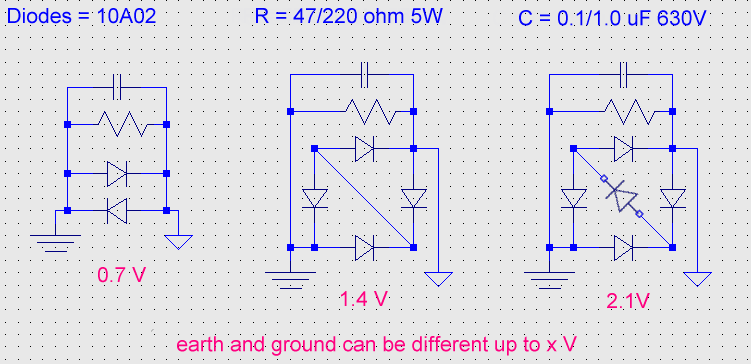 |
| for safety is better use 25A diode as D6025L. The cap is Wima MKP10 |
If you like to know more on the argument please read the 43 pages Understanding, Finding and Eliminating Ground Loops by Bill Whithlock (President and Chief Engineer of Jensen Transformers).
Interesting, OK, probably any of us have "the solution", better, but not after reading the 215 pages, also from Bill Whithlock: An Overview of Audio System Grounding and Interfacing. How many and how many things do we ignore?.
Donations if you have a Bitcoin wallet
If you have a nice fat wallet you can send a few cents to this code 1ETv1mJTZTB7EiXwZkucF2BTA512Rkaw6 maybe with a message (be careful to the transaction cost, send 0.1 and pay 0.01 is not a good idea).
1ETv1mJTZTB7EiXwZkucF2BTA512Rkaw6 <== my code , Thank you.
Donations if you have not a Bitcoin wallet
If you like this work and measures you can make a small donation of Bitcoin. You do not need a wallet to make a donation, indeed even those who have Bitcoin wallet is better to pass for a web site that "gift" currency since this does not have a transaction cost.
To make a donation you must use some of your web-time on a Bitcoin Faucet, please go to Kickasstraffic.com, enter my code 1ETv1mJTZTB7EiXwZkucF2BTA512Rkaw6 into empty cell and press "Start Earning", a new sub-page appear, do not touch other then the last 2 buttons in lower right corner "Surf Ads" and "Active Window Ads".
If appear a tweet asking to register use the lower right corner button "Close", solve the Captcha and proceed. Of course any next page if different but I suggest you to stay more time possible reading pages and advertisement to produce Bitcoin (1/100000 I suppose) for me.
Be careful, do not use roulette, dices, casino and other stealing web site, as claim of supposed infection. We use Kaspersky Free Antivirus by 2 years without problems.
1ETv1mJTZTB7EiXwZkucF2BTA512Rkaw6 <== my code , Thank you.
| In the last years at Universita' Degli Studi di Roma La Sapienza |
Dr. G. Visco already contract professor for Chemistry in Environment & Cultural Heritage into --> |
Corso di Laurea in: Scienze Applicate ai Beni Culturali ed alla Diagnostica per la loro Conservazione |