and ... more problems solved)
|
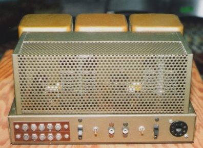
| fig.1, Acrosound Stereo 2020: on left a photo from Internet, to be restored on right after our work (new PCB and ... more problems solved) |
All trademarks mentioned and links are presented here for informational purposes only and to confirm statements made by the author. The author of these pages DOES NOT receive any remuneration from the mentioned brands and the listed links.
In any case if you decide to use the suggestions on this page you do so at your own risk. Repairing electronic equipments, even just opening it, can put your life at risk, so don't do it.
If you do not accept and/or not understand the statements in this disclaimer, written in blue, exit from this page immediately.
Everything exposed in this web page is only a suggestion, probably you won't obtain the aim from you prefixed following it.
Be carefull, a true collector is looking for a) original items without any replaced parts, and with all accessories b) or if a Critical Restoration has been done that it is possible to go back to the original version.
There are a few information on Philadelphia based Acrosound company. Probably the company start in 1950 (or 1949) with financial support of Herbert Keroes family (Keroes was an electrical engineering and audio enthusiast and like to build some equipments with a good designer, Hafler). Acrosound is a small company, produce principally kit, but also some complete equipments, probably their main business was sold transformers, famous up today. David Hafler pass to Dynaco, a larger company, in 1954.
You can find more on history reading an interview at D. Halfer in Vacuum Tube Valley journal, in 2000 (.pdf 1.3 MB).
Today the passing time clears the legend and leaves the fact: Hafler and Keroes invented the Ultralinear a giant step in output audio transformer. Acrosound transformer are the only brand available for Kit and DIY so good to produce a quality amplifier. But are a little under Marantz 8b, McIntosh MC30, Quad II, Jadis 80, Western Electric, (never available for DIY). From 1950 Unfortunately the complete equipments run the tubes too high in current and dissipation, the amply is very hot, and for sure can sound more better with a little re-design.
One of the main problems of Acrosound 20-20 is ........ the Quad II. The Quad have similar price, come as an evolution of Quad I, and previous there is the QA12/P, changing the tubes and with practically the same circuit. So to sell this small amp the company must reach almost 15 or 16W, cost less, use cheap tubes.
All is hot, the chassis, the tubes, the transformers. I never see the mono amp, the Stereo 20 (top left on this vintage advertise), but reading the schematic the power supply is better. Practically the stereo amp use the same supply of mono, but the problem of tube overload remain (or accentuate). One other problem of 20-20 is the space, there is no room for large modifications.
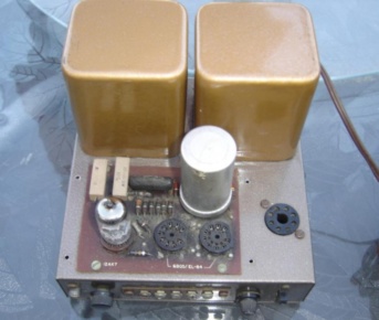  |
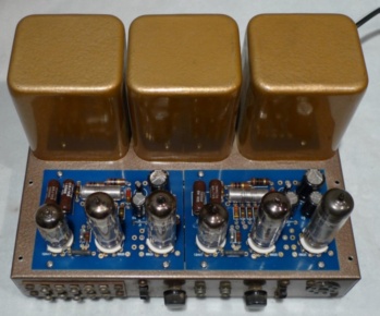
| fig.2, other problems in the original, the poor quality of the PCB, on the left see the large image of Stereo 20 mono (the best one), and lack of space on the right after a POOR restoration |
We can continue with the problems of this amplifier, as example the direct coupling, there is only one capacitor before the first tube, see a good choice but ..... the bias of the power tube depends by the gain of first tube !!. Is better report some links;
It's time to analyse the schematic and find a possible solution to obtain a good 11W power amplifier!
  |
| fig.3, on the left the schematic, here the large version on the right we are looking for the assembly instruction, send us please |
Why this amplifier sound so bad and go so hot? We have the reply for second query, the power tube are overloaded at 150% with modern 230V. The poor quality of sound is strange, Acrosound often work well, in this case probably there is a problem with the new PCB. THIS amplifier suffer parasitic oscillation (with the input closed with 1Kohm and a single 8ohm/50w wirewound resistor on output), the oscilloscope shown an oscillation at 200KHz, more hitting the 12AX7 tube.
The oscillation is present in the primary side of output transformer, different using x1 or x10 probe, different on anode, cathode, supply, a big problem.
The initial idea is change the voltage doubler and reduce the current on 6BQ5, after those measures I (asking the owner) pass to a complete disassembly.
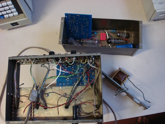 |
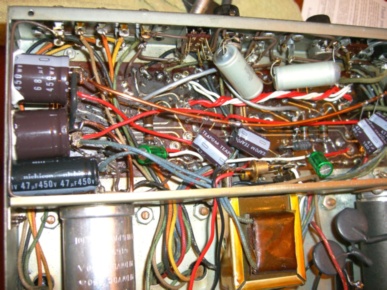
| fig.4, the disassemble of 20-20, found other problems: one choke wire is short, someone cut the output wires and filaments wire are all different |
Having all parts removed we pass to remove also all components from PCB. At this time we can use the measures doing in first test to make a new schematic to solve, I hope, the problems.
Before design a new schematics I think is better check the transformers. Acrosound transformers are famous up today and a price for real high (if you find it). Having the amp completely dismantle we can put in a table only one transformer and measure, with and without load, following the results (probably the only one measure on this transformer on all Internet):
If you like to know the measurement instruments see this page, and return here after reading.
Having the measure on the "original" amp and on their transformer we can design a new schematic. This one:
 |
| fig.5, modification schematics of Acrosound 20-20. Here in high resolution |
And here a discussion on modification, in no particular order:
Having the new schematic we can start to building. Be careful build a correct the ground is an Art, more on preamps, we like single point as Croft Supermicro, or a ground bar as HeathKit ID-22, or a distribute ground path as McIntosh MC30?
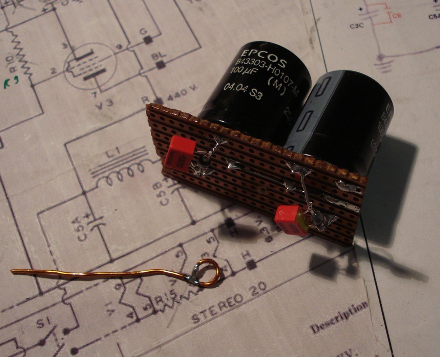  |
| fig.6, full wave voltage doubler, 2x 100uF/375V and BYV96E diode, with 3 snubber (be careful with voltage of capacitors, is not easy), all build in a Veroboard |
Starting with the build of High Voltage, using a good capacitor from JJ-electronics, and a Sprague Atom, NOS. The insulation must be done thinking to years, not days, so we use cardboard or Bakelite, not a plastic ready to dead (think to your woofer foam or rubber of tonearm).
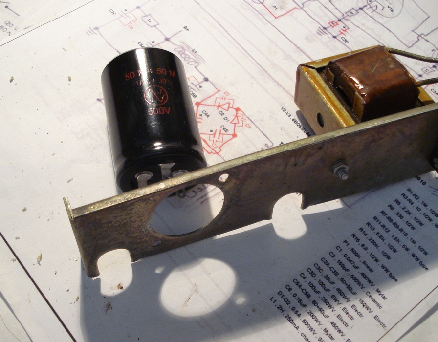 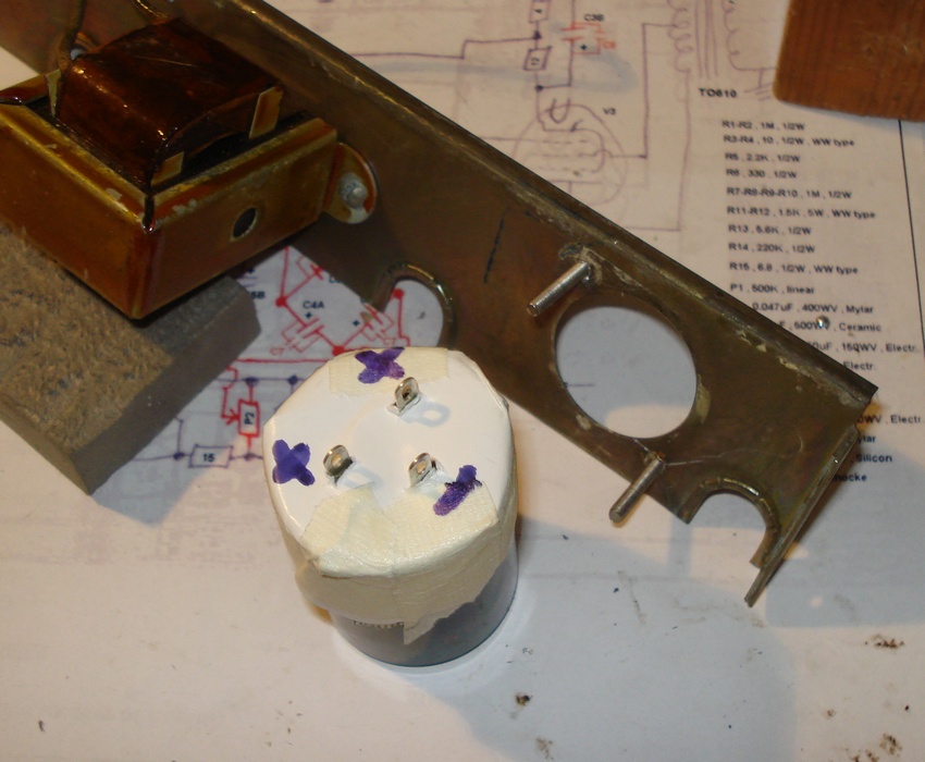 |
| fig.7, on the left the capacitor, 50+50uF/500V from JJ, on the right an insulation method for capacitor |
Next step was make links with choke, with other HV capacitor, with bypass and to mid voltage capacitor. R14-C3C is a π RC filter on HV, is better move away from PCB, see on next photo in upper right corner.
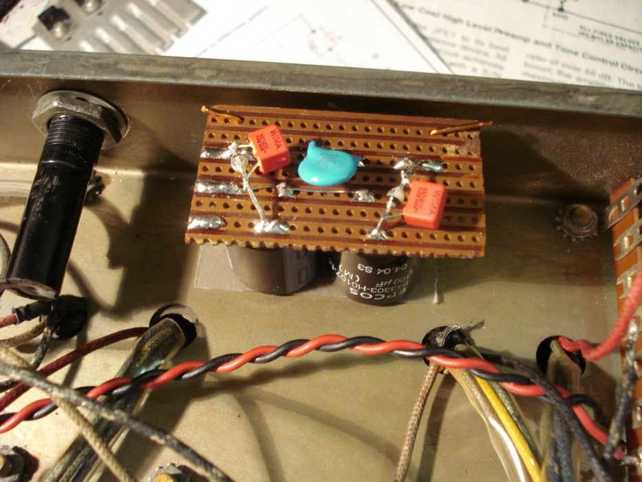
 |
| fig.8, all high voltage was ready, see the Wima 0.1uF as bypass |
It's time to pass to PCB. All components was removed, for every value a best selection was done (Dale, Holco, Vishay, Philips). Some paths was cut to insert the grid-stop, in place of R14 there is a small wire. All capacitors was moved in the bottom side of PCB. The capacitors suffer the temperature, NEVER put near a tube or transformer.
For the bypass of cathode capacitor we use our old idea, same capacitor, same brand, same type, same year, of course different values, in this case double of original, 100uF/100V and bypass is 0.47uF/100V, ALL Nichicon.
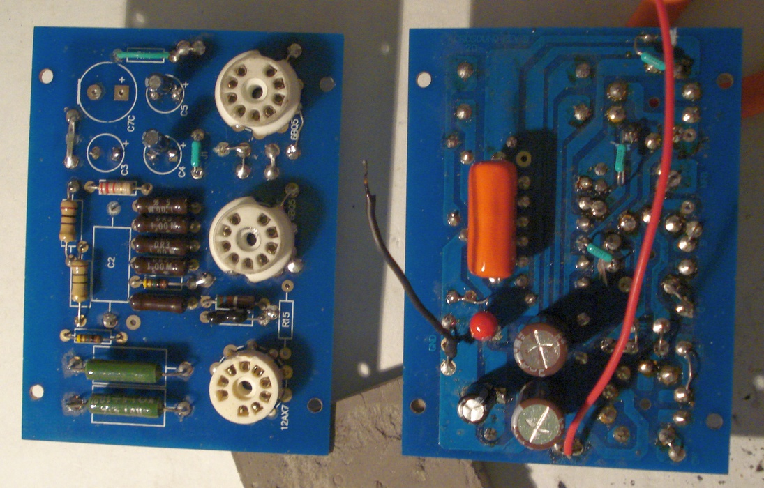 |
| fig.9, the 2 side of PCB after restoration, see C4-C5 of the bottom side and the bypass C4b and C5b on upper side, same brand, Here a zoom of PCB |
Finally we working on the MAIN modify, reduce the current on 6BQ5. We use cement resistors with power rating double of necessary, but ...... After 2 hours it was very hot, to solve we link with an aluminium grid on the case. It's a good solution after other 2 hours we can held a finger on the grid (after main voltage removed and wait 15 seconds).
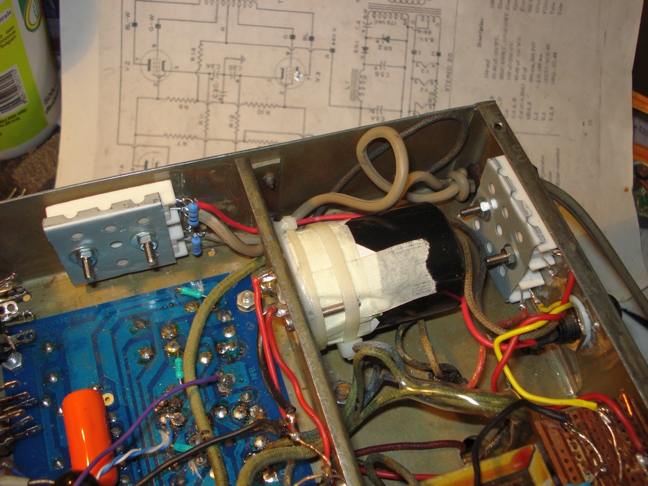 |
| fig.10, on the left the R on main voltage 225V, on the right the R on the HV from secondary of main transformer |
And finally we mount all components, with 180 degrees turn of PCB. In this position we can use the wires from output transformer to tubes, unfortunately the output wires are too short and we must use 2 terminal strips to do some links.
The supply circuit was reduced, we have not the voltage output on the octal plug, the voltage selector was removed and the mono-stereo selector was not used.
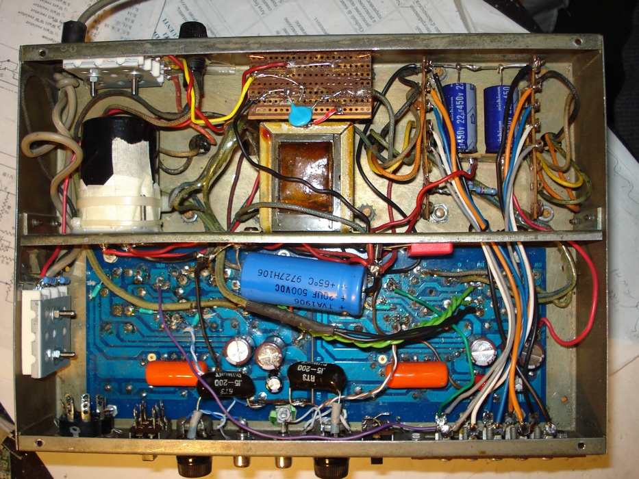 |
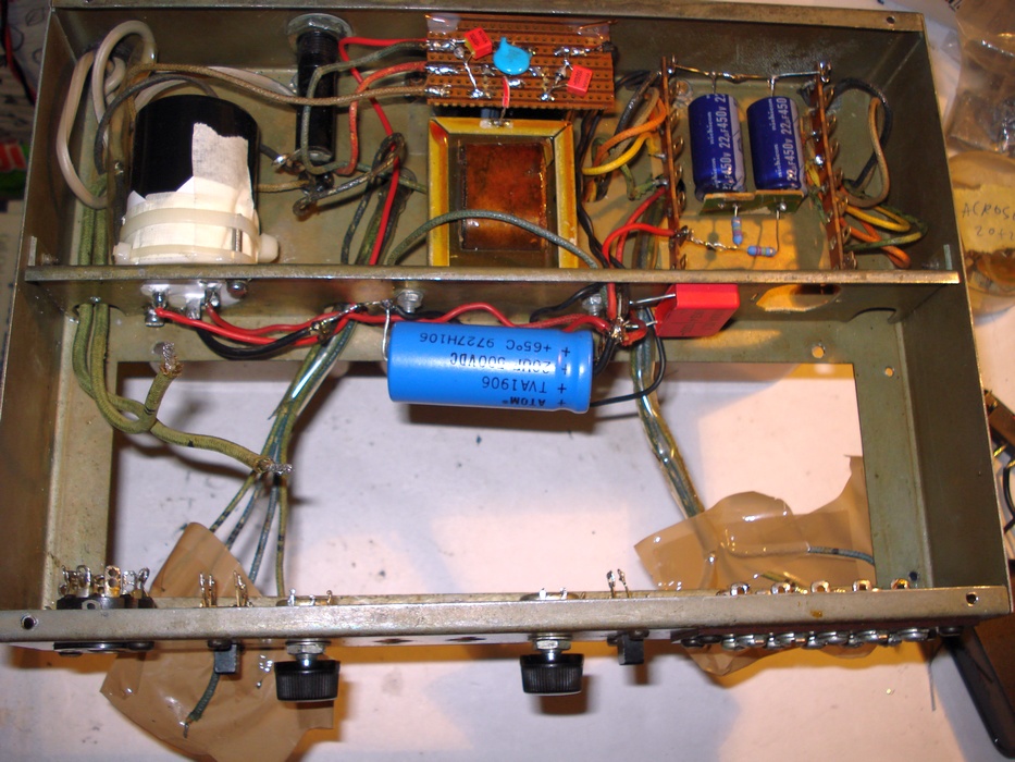
| fig.11, a view of the internal, see the wires, short as possible. for all photo if you "open image" you obtain a double resolution |
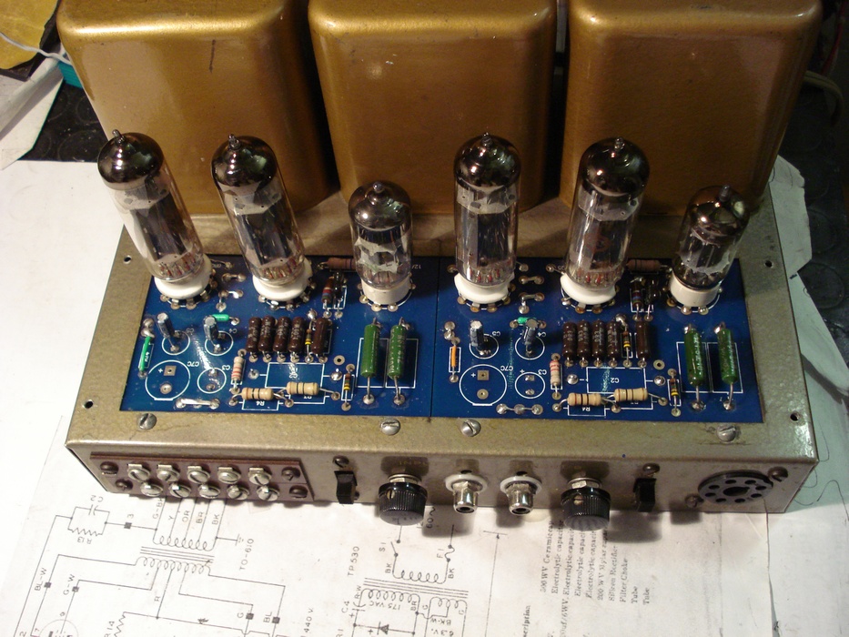
Following the external view, you can see the lack of practically all capacitors, put underside, the space under R11-R12 (glass green) to better dissipation and to make space for 6BQ5 current measure.
 |
| fig.12, potentiometers, RCA jack, and output screws are new |
Below the sinewave and squarewave of the Acrosound 20-20 as arrive on my desk. The 1KHz square wave show the parasitic oscillation. The sinewave already with 2.8V of output show some forms of distortion. Move the mouse on the figure.
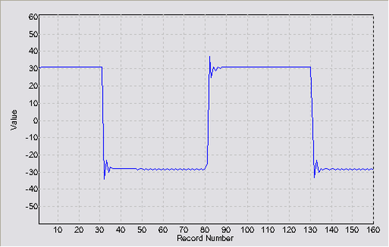 |
| fig.13, move the mouse over to see the sine wave (2.8V RMS on 8ohm, 1KHz) |
After modification we aspect a better response to squarewave and a more correct sinewave. Yes the results are interesting, see below. The power output go down to 11W RMS on pure 8ohm load measure at the very first distortion. Finally we stay inside the specification of producers. Below the new waveform.
The sinewave is near then perfect at 2.8V out, also the squarewave show only a little ringing and no more oscillation. Al measures are done with a 600ohm signal generator and with an 8ohm 50W wirewound anti-inductive resistor on the 8ohm output without cable.
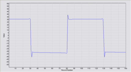 |
| fig.14, move the mouse over to see the sine wave (2.8V RMS on 8ohm, 1KHz). Click here for large view, squarewave, and sinewave |
More suggestions:
The modification is not easy and fast, I spent about one year for this. Use patient, spent one hour to remove the PCB, next week one other hour to remove the doublier, and so on.
Sorry, I have a Marantz 8b vintage and an 8b reissue, two MC60, in previous month I repair an Audio Note with 300b, and in previous page you can find a 1952 tube amp from BBC.
Also, for a long time friend, I restore a final version of Quad II, all resistors and capacitors changed and added some wire in Ag from transformer to banana socket, the 230V out from behind, and so on.
Do not ask me for the sound of this amp, quite well after restoration but .....
Donations if you have a Bitcoin wallet
If you have a nice fat wallet you can send a few cents to this code 1ETv1mJTZTB7EiXwZkucF2BTA512Rkaw6 maybe with a message (be careful to the transaction cost, send 0.1 and pay 0.01 is not a good idea).
1ETv1mJTZTB7EiXwZkucF2BTA512Rkaw6 <== my code , Thank you.
Donations if you have not a Bitcoin wallet
If you like this work and measures you can make a small donation of Bitcoin. You do not need a wallet to make a donation, indeed even those who have Bitcoin wallet is better to pass for a web site that "gift" currency since this does not have a transaction cost.
To make a donation you must use some of your web-time on a Bitcoin Faucet, please go to Kickasstraffic.com, enter my code 1ETv1mJTZTB7EiXwZkucF2BTA512Rkaw6 into empty cell and press "Start Earning", a new sub-page appear, do not touch other then the last 2 buttons in lower right corner "Surf Ads" and "Active Window Ads".
If appear a tweet asking to register use the lower right corner button "Close", solve the Captcha and proceed. Of course any next page if different but I suggest you to stay more time possible reading pages and advertisement to produce Bitcoin (1/100000 I suppose) for me.
Be careful, do not use roulette, dices, casino and other stealing web site, as claim of supposed infection. We use Kaspersky Free Antivirus by 2 years without problems.
1ETv1mJTZTB7EiXwZkucF2BTA512Rkaw6 <== my code , Thank you.
| In the last years at Universita' Degli Studi di Roma La Sapienza |
Dr. G. Visco already contract professor for Chemistry in Environment & Cultural Heritage into --> |
Corso di Laurea in: Scienze Applicate ai Beni Culturali ed alla Diagnostica per la loro Conservazione |